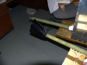
Firewall Insulation 2
- Details
- Written by Kevin Horton
- Hits: 5040
An order of misc hardware arrived from Wicks last week. There were a bunch of small tasks that were on hold because I was waiting to get this hardware, so I attacked them as soon as it arrived. But, almost without fail, I found that I could not completely finish those tasks, as I found that I needed yet another piece of unexpected hardware, or that the hardware I had ordered didn't in fact do the job. Arrgh!
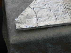 I did make some progress on the firewall insulation. I got two large pieces trimmed to fit, and then worked on sealing the edges with aluminum tape.
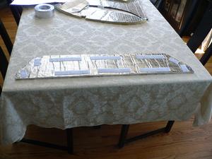 One large piece had long straight edges, so it was easy to seal. Velcro strips will hold the insulation against the firewall, yet allow it to be removed if required.
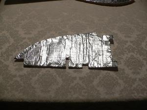 But, several other pieces have many cutouts to go around various things, so it is very tedious to trim the tape and get it to go around the complicated shapes.
Firewall Insulation
- Details
- Written by Kevin Horton
- Hits: 8301
Way back in 2005, I made my first aborted attempt to install firewall insulation. I stopped when I discovered that the stuff I was installing burned fiercely when it was exposed to a flame, producing great quantities of thick black smoke. Since then I have been looking for a better material.
Someone eventually suggested I check into the insulation sold by Flightline Interiors. I called Abby, and asked about how fire resistance it was, and whether it had been tested against the criteria of FAR 23.853 (design standards for type-certificated light aircraft - we don't have to comply with them, but they provide a useful benchmark). She wasn't sure about the FAR testing status, but she believed the material was fairly fire resistant. She offered to send me a sample.
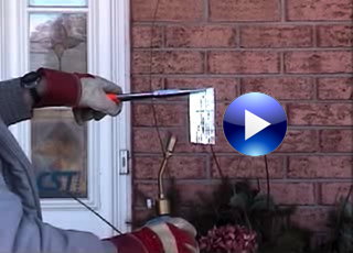 The sample arrived about three weeks ago, along with an information sheet. I learned that it was 3/8" thick Thermozite Plus with foil on each side, and Google told me that it was very popular in the automotive industry, and that it was supposedly fire resistant. The data sheet claimed that it met the Federal Motor Vehicle Safety Standard 302, whatever that was.
The following weekend I enlisted Terry's assistance to document a rudimentary burn test. I'm not equipped to do a proper FAR 23.853 burn test, but I tried to do the closest thing I could, considering the small sample size. I found that the inner material would burn when subjected to a direct flame (this is allowed, as long as it quickly self-extinguishes when the flame is removed). A small quantity of black smoke was produced, and the flame went out very quickly when I removed the torch. All in all it was a big improvement over the first material I tried, and it probably comes close to FAR 23.853 criteria.
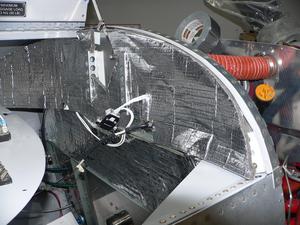 This evening I started to install the Thermozite firewall insulation. I've got the upper most section mostly fitted, but I've got a few more tweaks to do. I'll use some aluminum tape to finish the edges, and I'll attach it with a few Velcro strips so it can be removed if required. Yes, I suspect the Velcro will burn, but I won't be using very much of it.
Aileron Control Rod Boots
- Details
- Written by Kevin Horton
- Hits: 8253
I got a few more small items done this week. This weekend, I had planned to bond the engine preheater pad to the oil sump, but I got distracted by the box that arrived on Friday from Flightline Interiors, containing aileron pushrod boots and firewall insulation. I completely forgot about the engine preheat, and attacked the aileron pushrod boots.
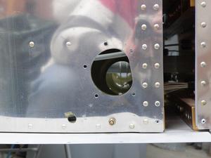 The aileron pushrods go from the bottom of the control stick weldment, in the middle of the fuselage, through holes in the fuselage into the wings. Apparently a large quantity of air will travel from the wing into the fuselage through those holes. This is not a big deal in the summer, but it causes a very cold draft in the winter. The standard solution is to install fabric cone-shaped boots, with the point of the cone on the aileron control rod, and the base at the hole in the fuselage. The fabric blocks the air flow, but allows the control rods to move freely.
I stumbled across Flightline Interiors when I was looking for firewall insulation. I had seen many positive comments from Abby's customers, but had never visited her web site. When I was looking for firewall insulation, I discovered that Abby also sold aileron boots. The price was right ($19), and it looked like a way to save a bit of time, so I ordered a pair.
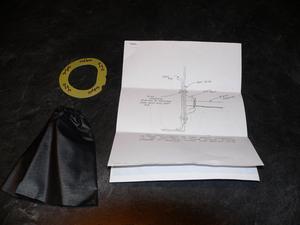 I was a bit chagrined when they arrived to find that the kit does not include the metal rings that are used to attach the outer part of the boot to the fuselage, nor is any hardware included. I had lots of spare metal and hardware, but I had somehow expected that stuff to be included. To be fair to Abby, the description on the web site is quite clear - I had just not read it properly. I should have woken up when I thought "Wow, $19 is a very good price for aileron boots, metal rings and hardware".
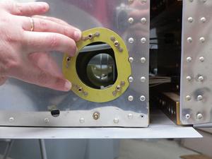 Heads up to any other RV-8 builders using this kit - the paper template for the metal rings is a bit small. I figured that out before I cut any metal, and it only took a few minutes to make my own, correctly sized template, so no harm done. I drilled five holes to mount each ring to the fuselage. The top hole is where a rivet used to be. The rivet would have been in the way, so I drilled it out and used it as a screw hole. The instructions show the nutplates being riveted to the fuselage, but I decided it would be easier to do this retrofit if the nutplates were on the ring.
 The small end of the aileron boot has some elastic sewn into it, so it will fit tightly over the aileron control rod.
I need to get some spray adhesive to hold the boot fabric in place while I screw the rings on to the fuselage, and this job will be done.
Progress on Many Small Items
- Details
- Written by Kevin Horton
- Hits: 3883
The last few days I've assiduously attacked the smaller items on the big To Do list:
- Fix chafing on static line at remote compass mount
- Fix chafing between fuel vent line and wire bundle in RH landing gear box
- Torque screws on back of prop governor
- Torque some oil sump nuts where I had removed them to install Adel clamps
- Install ground line for strobe lights
- Install ground line for electronic ignition cable shields
- Permanently install GPS antenna
- Attach instrument panel ground tab block to bulkhead, after removing the piece of wood that was originally intended to insulate it from the bulkhead (the original plan had a ground wire going from the instrument panel ground tab block to the firewall ground block, in an attempt to avoid ground loops, but that ground wire created a single point of failure that would kill everything on the instrument panel - bad idea)
- Install correct bolts in mixture cable bellcrank mount
- etc
Some of the items only took a few minutes to do, once I had spent a half hour figuring out what the cryptic description meant. Some of them took a couple of hours. The list actually got quite a bit shorter, which is a great feeling.
There is another bunch of small items that I can do, once I receive various small hardware items that I've ordered. My Reiff engine preheat system arrived on Friday, so I'll be working on that over the next few days. I'm also waiting for firewall insulation and aileron boots to arrive from Flightline Interiors.
New Inverted Oil System Separator Tank
- Details
- Written by Kevin Horton
- Hits: 5831
A little while back I wrote about "One of Those Weeks", where seemingly everything goes wrong. I thought I had escaped from under that black cloud, but apparently not.
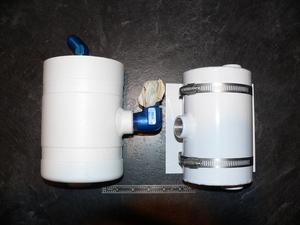 The replacement inverted oil system tank arrived on Monday. Raven Aircraft makes two different size tanks - I bought the smaller, 4" diameter one. The Raven Aircraft tank is the smaller one, on the right.
Monday evening I started to fit the new tank. I figured out where I was going to mount it, then I figured out what angle the bottom fitting needed to be at. I put some Teflon paste on the threads, being careful to not get any on the last thread, as you don't want any of this stuff getting into the oil system, where it may block an oil passage. I was so careful to not get any on the last thread, that the last two threads ended up without any Teflon on them.
I screwed the fitting into the mounting boss, and it started to come up tight just after I passed the required angle. You can't back off these fittings, as they use a tapered thread. Back them off and you risk a leak. So, I kept tightening it, needing to get it almost another full turn. But, the fitting got really, really tight before I made it to the required angle. OK, now I needed to remove it, put some more Teflon paste on it, and try again. But, it was really, really hard to unscrew, and it doesn't get much easier as I unscrew it, which is very abnormal. After getting it out, I can see that there had been galling between the aluminum fitting, and the aluminum boss. A chunk of the threads on the fitting had welded it self to the threads in the boss. I had just screwed up my expensive new oil separator tank. Down tools. Go into the house and have a beer.
I did some research, and learned that the AN823-10D fitting I was using has a 1/2" pipe thread. I called my local hardware store, and found that they had a 1/2" pipe thread tap in stock. It wasn't cheap, but it was a lot less money than a new tank.
Yesterday I was able to carefully thread the tap into the undamaged portion of the threads, and managed to re-cut the damage portions. The fact that the threaded hole is tapered was a big advantage, as I was able to run the tap in a bit deeper than the hole was originally tapped, and this put a new surface on the all the threads. I was careful to hold the tank so the boss was facing down, and the tap was coming up from the bottom, to ensure than none of the swarf got into the tank.
I pulled a new fitting from the stock, and put it into place, being extra careful. It was just starting to come up tight as I approached the required angle, and I didn't tempt fate by trying to get another turn out of it. This tank runs at low pressure, so there is little risk of leakage once the Teflon paste hardens up.
Modified Cabin Heat Muff 3
- Details
- Written by Kevin Horton
- Hits: 5600
Awhile back I started trying to sort out a better place to put a second cabin heat muff. I eventually ordered one from Rick Robbins, and it arrived a few weeks ago. Today I finally finished fitting it, and installed the SCAT tubes.
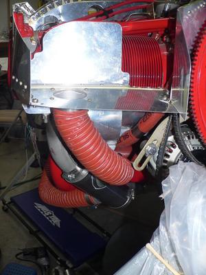 The custom 7" long muff will get its air from a hole in the right baffle floor.
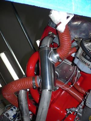 This shot is looking up, with the air coming into the muff on the right, and exiting on the left.
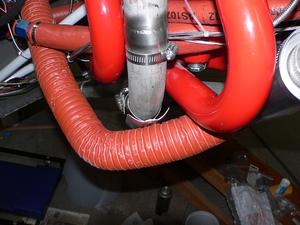 I've got a heat shield between one of the exhaust pipes and SCAT tube. This piece of SCAT should probably be shortened a bit. This piece of SCAT just touches the cowling. I should probably go down to 1.5" diameter SCAT, as this would give me another half inch clearance, and I've got a report from an RV-6 flyer in Minnesota who reports that if too much cold air is going through the heat muff that you don't get as much heat as you do if you restrict the amount of airflow. He has 2" SCAT tube, found found that he needed to block off 80% of the opening. He thinks that 1.5" diameter SCAT is more than big enough. But, I'll worry about that after I get flying. No more mods that aren't strictly required.
I knocked off several more smaller items on the big To Do List. But I found a few more items to add to the list, so the net gain was only about two items.
