RMC 25 Year Reunion
- Details
- Written by Kevin Horton
- Hits: 3358
This weekend was reunion weekend at the Royal Military College in Kingston, Ontario. This year was my 25 year reunion, so Friday afternoon I drove down to Kingston. I watched the first year class do the obstacle course, then went to a class meet and greet. We had a very good turn out, with about 70 of the 155 remaining classmates attending (four are no longer living, which is a surprising small number in 25 years). There were several more who wanted to come, but were serving in Afghanistan.
It was great to get caught up with many people that I hadn't talked to in 25 years. The vast majority looked almost identical to 25 years ago, except for a bit of grey hair. But there were two who completed threw me, and I had no idea who they were until they said their names.
I came back home late on Saturday. All in all, it was a great reunion. But depressing how quickly 25 years have flashed by.
Today's Lesson - Short Cuts
- Details
- Written by Kevin Horton
- Hits: 3105
Several months ago I saw an e-mail list post about a gap between the right aft cylinder and the aft baffle wall. I looked at my baffling, and sure enough, there was an area at the base of the cylinder with a gap an inch wide. A whole bunch of air could escape through that gap rather than going between the cylinder fins. Not good. There was a tab on the baffle that was supposed to have been bent over to fill that gap, but I missed it.
I decided that it would be a major pain in the butt to remove that baffle piece to bend the tab, so I decided to save some time and effort by bending it in place. But, there was very poor access, so I was only able to get it bent a little bit. I found a short piece of wood to use as a tool, and managed to get it bent a bit more, but still not enough. I probably spent three hours fiddling with this problem over several different evenings.
Friday morning I finally bit the bullet and decided to simply remove that piece of baffle, rather than try to bend the tab in place. It only took about 20 minutes to remove the baffle, five minutes to bend the tab, and five more minutes to get the baffle back in place. Except for one attachment screw which was behind the oil filler tube.
Try as I might, I couldn't get that screw back in place. The oil filler tube was safety wired in place, so I didn't want to remove it. I fiddled with that screw for about half an hour, using pliers, Phillips bits on a universal joint, one finger from each hand - no way could I get it in place.
This afternoon I decided to remove the oil filler tube so I could get a straight shot at that screw. Five minutes to remove the tube, one minute to put the screw in, and ten minutes to reinstall the oil filler tube. I would have saved several hours of screwing around if I had simply decided to do this job the correct way, rather than trying to use short cuts. I spent needless hours trying to bend that tab in place, and trying to replace that screw with the oil filler tube in place.
I am glad that I decided to install nutplates at critical places in the baffles. The basic design has the baffles being completely riveted together, which means that they can't be removed without drilling out rivets. I can simply remove some screws to disassemble my baffles.
Windscreen Fairing - Not So Bad
- Details
- Written by Kevin Horton
- Hits: 4338
This week I took care of a few minor items, including a small gouge on the prop blade root. I had put this tiny gouge in the blade root when fitting the spinner. It wasn't completely clear whether the gouge actually went into the aluminum, or was only in the paint, but I could risk ignoring it. The prop blade root is under a lot of stress, and the imbalance resulting from a blade failure would almost certainly cause the engine mount to fail, with the resulting aft CG leading to a fatal crash. I used very, very fine sand paper to blend out the gouge over a long distance, then used an Alodine 1132 pen to put an anti-corrosion coating on the aluminum. Today I sprayed the area with Tempo epoxy prop blade paint. The resulting repair is pretty much undetectable.
This week I also did most of the work to fabricate a doubler for the belly mounted COM antenna. Although these antennae typically require an internal doubler to ensure no cracks develop in the skin, for some stupid reason I forgot to install one. I had to remove the antenna, drill out the platenuts, and fabricate an 0.032" doubler. Sometime this week I need to get Terry to help me dimple the holes in the fuselage where the doubler will mount, then we can rivet it in place.
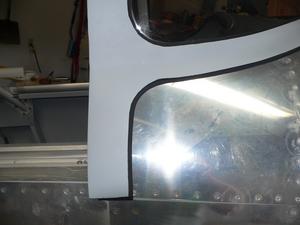
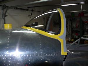
 Today I pulled off the vinyl tape around the windscreen fairing and took a closer look at the seam filler around the edges. I'm not completely satisfied with it, but it looks better than I thought. I'll do a bit of touch up to fill in a few small low spots to smooth it out a bit.
Windscreen Fairing - Repair Successful
- Details
- Written by Kevin Horton
- Hits: 3864
I was a bit demotivated after last weekend's windscreen disaster, so I didn't get much work done this week. Yesterday I redid the worst parts of the seam filler around that fairing, and finished the parts that I had not yet started. It went much better. The trick was to do it in small sections, so I could pull off the tape on the windscreen before the seam filler had skinned over. I will have a bit of touchup work to do once the new filler fully cures, but I am now confident that I can end up with at least a minimally acceptable transition from windscreen to fairing.
I screwed up trimming the piece of rubber inner tube that does the transition from the cowling to plenum chamber, so I had to make it again, for the fourth time. Grrr.
Windscreen fairing - Major frustration
- Details
- Written by Kevin Horton
- Hits: 3837
I'm pretty frustrated right now. Today did not go well.
 On Friday I purchased some auto body seam sealer to use to fair in the edges of the windscreen fairing. Today I attacked that job, and it didn't turn out well at all. I had put some vinyl tape on the outer surface of the windscreen fairing and on the windscreen where I wanted the edge of the bead of sealer to be. When I put the sealer in place I tried to keep it just on the area I wanted, but some of it spilled over onto the vinyl tape on the windscreen. When I was done, I pulled the vinyl tape off, but the sealer had already started to skin over, and pulling the tape off left a very ragged edge in many places. I was really freaked out, as I had this ugly disaster on the windscreen, and I didn't even want to think about having to buy a new one, and redo all that work.
I took a deep breath, and looked closer. The left side (which was done first), was completely ugly. The right side, was much better, as I was much more practiced with the seam sealer, and had much less sealer on the vinyl tape. I decided to see if kerosene, one of the very few solvents that is safe to use on plexiglas, would soften the sealer. I was greatly relieved to see that it slowly dissolved the sealer. It took quite a bit of time, but I was able to remove the bulk of the sealer on the left side. I'll give the remaining sealer a few days to set up, then I'll have to try again.
Pre-punched RV-8 Kit
- Details
- Written by Kevin Horton
- Hits: 4477
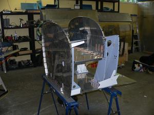
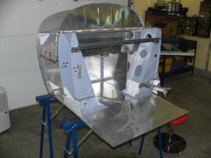
Saturday I visited RV-8 builder Ken Tattersal in Metcalfe. Ken started his kit about eight months ago, so he has what is known as the pre-punched kit. This means that both the skins and the underlying structure are punched with pilot holes. You can cleco the parts together, then use a drill to enlarge the holes to the final size. Earlier kits, like mine, had pilot holes in the skins, but no holes in the underlying structure. You had to draw centre lines on all the flanges on the structure, get every thing clamped in place in a jig, ensure you could see the centre lines on the flanges through the holes in the skins, then drill the rivet holes. The new kits don't require a jig, nor do they require the painstaking measuring, aligning and cross checking before you drill the holes. You basically grab the pieces, and some cleocs, throw them up in the air and it assembles itself before it hits the ground :)
 Here is the forward fuselage, from the firewall to the forward spar area. No jig was needed. It was assembled on a couple of steel saw horses. The fuselage is assembled in three sections - forward fuselage, cockpit area and aft fuselage. First the bulkheads and internal structure are riveted together, then the longerons are slipped in place and the skins are riveted on. Ken is doing a beautiful job, and he will have a great aircraft when he is finished.
 Ken told me that it took him 3.5 hours to assemble the landing gear boxes. This included the time to deburr all the edges, cleco the parts together, final drill the holes, deburr the holes, prime and rivet. I spent more than 3.5 hours just scratching my head trying to figure out how to deal with some of the problems I had with my landing gear boxes.
