Alternator Belt Tension
- Details
- Written by Kevin Horton
- Hits: 3874
Earlier this week I adjusted the alternator belt tension, torqued the tension arm and pivot bolt, and safety wired them. The B&C installation instructions didn't have any info on the alternator belt tension, so Google to the rescue. Thanks to Mickey Coggins for putting the info where Google found it, and thanks to Vern Little for doing the original research and making the posting on the VAF WWW forum.
Vern Little's VAF WWW post:
Belt deflection is an unreliable method of tightening the belt.
Instead, use a torque wrench on the pulley belt and adjust the tension so that you get about 12 ft-lbs before the belt slips.
A loose belt can lead to under-voltage or over-voltage from the alternator. Overvoltage is caused by the regulator trying to force more output from the alternator while the belt is slipping. When the belt grabs, it puts a surge of voltage on the bus.
Please don't ask me how I found out!
ref Lycoming s. i. 1129A
Lycoming SI 1129A Accessory Drive Belt Tension
New 3/8 inch wide belt 11-13 ft/lbs 132-156 in/lbs. used 3/8 inch wide belt 7-9 ft/lbs 84-108 in/lbs
New 1/2 inch wide belt 13-15 ft/lbs 156-180 in/lbs. used 1/2 inch wide belt 9-11 ft/lbs 108-132in/lbs
Vern Little 9A
Pitot Tube Connection
- Details
- Written by Kevin Horton
- Hits: 6928
I attacked the pitot tube line connection at the pitot tube this week. I originally had a fairly complicated plan that I had borrowed from another builder web site, with many different fittings required to make the transition from the pitot tube to the nylon pitot line. Then, when I pulled out my tray of #4 plumbing fittings, I spied a fitting that I had forgotten I had, and I realized that it would allow me a much simpler transition.
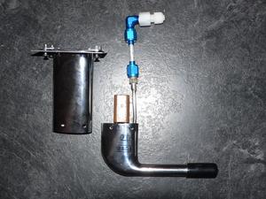 I'm using a pitot tube mount I purchased from Warren Gretz at Gretz Aero. The pitot line connection on the pitot tube will end up inside the pitot tube mount, so it needs a short piece of aluminum line with flared fittings on each end to allow a connection in the clear above the pitot tube mount.
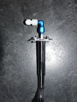 I connected an AN822-4D elbow at the top of that short piece of aluminum line, with the pipe thread on the AN822 screwed into a 266-N female Nylo-Seal connector. The nylon Nylo-Seal pitot line will connect to the 266-N connector.
I managed to drop the pitot tube, and broke the brown (Bakelite?) electrical connector. I glued it back together with 5 minute epoxy, and an aluminum reinforcement. But, now I am concerned that the high temperature from the pitot heat will soften the epoxy. So, I'll purchase a new connector. So far, the only place I have found that sells them is Aircraft Spruce, and that little connector costs $58. Drat.
Tonight I also completed two more little things on the big To Do List, but I found two more that I needed to add - net change one item.
Windscreen Fairing Installed
- Details
- Written by Kevin Horton
- Hits: 5019
I got a few small items done this week, and two larger items.
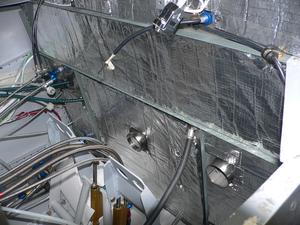
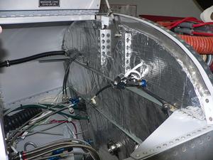 I spent several hours finishing off the sound and heat insulation on the firewall. The hardest part of that job was removing the adhesive from the industrial grade stick-on Velcro that I had used on the first aborted attempt at installing firewall insulation. I was able to use most of the original Velcro on the firewall, but there were several pieces that turned out to be poorly placed, so I had to remove them. I had been worried that the adhesive wouldn't stick well to stainless steel, but that turned out to not be a problem. I was able to peel the Velcro off, with considerable effort, but there was a thick layer of adhesive left behind. I finally discovered a wax and grease remover that would soften it slightly, so I could remove a few microns at a time with a scraper.
I had a minor disaster while installing the firewall insulation. The piece that goes at the top right is shaped so the inside edge of the forward baggage bay door just clears it. After I installed it, I decided to close the door to confirm that the insulation wasn't interfering with hit. The door seemed be hitting something at the front edge, which I assumed must be the insulation, so I gave it a rap with my hand. There was a loud SNAP, and the door closed. Oh oh. That didn't sound good. It had been a long time since I had closed the baggage door, and I had forgotten that it has a slight twist in it. You have to twist it a bit as you close it, or the forward edge hits the UHMW plastic block that the forward latch rod goes into. The edge of the plastic snap ring had hit the edge of that block, which is why the door didn't want to close, and the snap ring broke when I gave the door a rap with my hand.
To further complicate things, for some strange reason, the short screw that fastens the latch rod arm on the back of door lock had come out, and the latch rod arm had come off, which allowed the forward latch rod to slip inside the door. I had actually seen that the screw was missing a week ago, but I hadn't comprehended what I had seen until just now. It is weird that it took my brain a week to process what my eyes had seen.
The latch mechanism was designed to be assembled before the inside skin of the door was pop riveted in place. Now I had to repeat this on an already assembled door. Fortunately, I had a spare screw for the lock, and this time I put some Lock Tight on it. It took quite a bit of fiddling around, but I was able to get the latch assembly reinstalled.
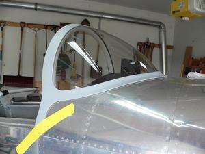 Yesterday I cleaned the windscreen, as it had some residue from the 3M 471 vinyl tape that I had put on it when I built the fibreglas windscreen fairing. Today I installed the windscreen, scuffed the aluminum that would underlay the fairing, and cleaned and scuffed the inside surface of the fairing. Then I gritted my teeth and put a 3/16" bead of Lexel adhesive where the fairing would go, and popped it in place. I used some 3M 471 tape to secure it in place.
I was very worried how it would turn out, as a major problem would probably require me to buy a new canopy to make a new windscreen, and make a new fairing. This would be a major, major setback. I was very nervous when I installed the fairing, but it looks perfect. Whew. There is very little gap between the fairing and the windscreen or fuselage, and the fit is perfect. I'll give it a couple of weeks to fully cure, then I'll track down some auto body seam filler to seal the small gaps between the fairing and the fuselage and windscreen.
The RV-8 instructions would have the builder lay up the windscreen fairing in place, and never remove it. I was worried about how I would get a nice edge on the fairing without scratching up the windscreen with the sanding. I borrowed my approach from John Huft - he had the idea of laying the fairing up on tape, and removing it for sanding, then bonding it on later
Note: John Huft used Lexel to bond the fairing to the Plexiglas, and fibreglas resin to bond it to the aluminum. The Lexel application info seemed to indicate that it might not have quite as strong a bond to aluminum as it would to Plexiglas and fibreglas, so I decided to do a test. I cleaned and scuffed up pieces of fibreglas and aluminum, then bonded them together with Lexel. I checked the joint 18 hours later, and the bond seemed to be very weak. I decided that I would have to use fibreglas resin. But yesterday I took another look at this joint. It had been about about three weeks since I had bonded the pieces together, and now the bond was very, very strong. The bonded area was only 1.25 square inches, but I could not pull them apart, even though I had moved the bond 18 hours after it had been made. Lexel appears to make very strong bonds, but it takes a long time to fully set up.
Brake Lines 2
- Details
- Written by Kevin Horton
- Hits: 5131
I had really expected to get a lot of work done during the week last week, but four of the evenings had some major unexpected event that disrupted RV-8 work.
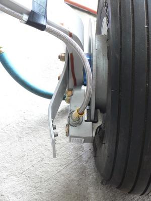
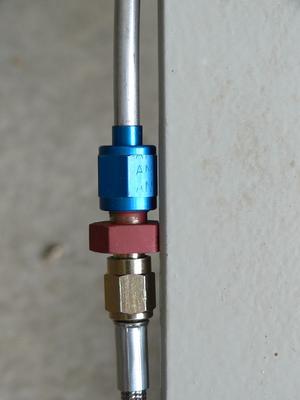 I was able to finish off the installation of the Teflon brake lines at the bottom end of the landing gear legs. The space inside the landing gear fairing reduces as you move aft of the landing gear leg, so I had to grind off most of the hex in the middle of the AN919 fitting that joins the aluminum line to the flexible hose.
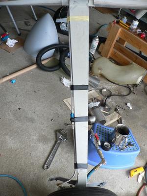 The aluminum line, fitting and flexible hose are secured to the landing gear leg, with sections of tough plastic line between the tape and the landing gear leg. I've used vinyl tape for the moment, but I'll replace that will something more durable.
I also removed the prop so I could change the alternator belt. Originally I had installed a converted automotive alternator, but I later decided to replace that with a B&C Specialties alternator, which needed a different belt. I had been putting off doing this task, as I didn't have a ready way to support the prop while I removed it and reinstalled. I could borrow the engine hoist that I used the first time, but the hoist owner has moved well outside Ottawa, so it would have take at least two hours to obtain the hoist, and another two hours to return it. But Jim, a coworker, and his son, offered to lend a hand. They supported the prop while I removed and reinstalled it. Yesterday I torqued the prop bolts, but I still have to safety wire them.
Brake Lines
- Details
- Written by Kevin Horton
- Hits: 3981
I've been on the road essentially non-stop since Friday the 15th. Terry and I went to the Niagara wine region from the 15th to the 18th, and I was in Phoenix from the 20th to the 23rd.
Today I got a small amount of work done on the brake lines. A while back I managed to hit the aluminum brake line that runs down the back of the left landing gear leg. The impact was hard enough to put a bit indentation in the brake line. I decided to take advantage of this screw up by replacing the bottom section of the brake lines with sections of #3 metal-braided Teflon hose. The pre-made #3 lines and the fittings came from Pegasus Auto Racing.
I got this task about two thirds complete. And I discovered one more item to add to the big To Do List, so net progress was minus one third of an item.
I should be in town for the next week, so hopefully I can make some progress.
Drain Hoses and Oil Pressure Line
- Details
- Written by Kevin Horton
- Hits: 5071
I installed the sniffle valve earlier this week, and yesterday I finished installing the drain line from the sniffle valve to the back of the cowling. The sniffle valve allows any fuel that collects in the intake manifold after shutdown, or a flooded start, to drain out.
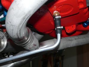 The sniffle valve is designed to have a 3/8" ID flexible rubber hose attached to it. This hose would have to run very close to the exhaust pipes, so I decided to transition to aluminum tubing.
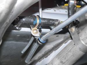 I hung the aft end of the aluminum tubing from the exhaust system hangars.
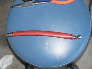
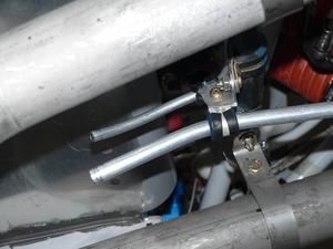 I also attached the drain line from the fuel pump. Normally, this drain line should have no fuel coming from it, but if the diaphragm develops a leak, the fuel needs to be routed to a safe place. I attached the bottom end of that drain line to the same place as the sniffle valve drain was supported. I used a piece of rubber hose between the fuel pump and the aluminum drain line to take care of vibration and the movement of the engine.
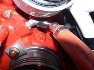 I also replaced the oil pressure line with a piece of Teflon lined hose from Pegasus Auto Racing Supplies. I cut the original hose a tiny bit too short, so there was no slack in the line at all. The movement of the engine on the engine mount would have put very high tension on the line, as the other end as attached to the oil pressure sender on the firewall, and the line would have failed. For the new line, I put a 45° fitting on the end to keep it further away from the engine mount. I decided to go with Teflon lined hose as they have a very long life, whereas the original hose I used is supposed to be replaced every few years. The fittings on the Aeroquip hose from Pegasus assemble very easily - much easier than the fittings on the rubber line hose I purchased from Aircraft Spruce.
