COM Antenna Doubler
- Details
- Written by Kevin Horton
- Hits: 4445
A while ago I realized that I should have put a doubler on the inside of the skin where the COM 1 antenna mounted. I removed the nutplates, fabricated a doubler, and alodined it, using an Alodine 1132 pen (Alodine is a type of passive conversion coating to prevent corrosion on aluminum). Today Terry helped me dimple the holes on the skin and rivet the doubler in place.
I also laid up the fibreglas for the plenum chamber transition on the left side of the cowling. I also studied the 12" registration marks, and figured out exactly where they need to go on the rear fuselage, so that they do not end up on top of one of the rear fuselage static ports. And, Terry did a bunch of work on the upholstery for the fabric covered cockpit side panels.
Airframe Grounding Points
- Details
- Written by Kevin Horton
- Hits: 4703
A few weeks ago I saw a posting on the Van's Air Force forum about the correct hardware to use to attach grounds to the airframe. The RV airframe is made from aluminum. The ring terminals on grounding straps are typically tin plated copper. When you put dissimilar metals in contact, there is the possibility of galvanic corrosion. If there is electrical current flowing, this increases the chance of corrosion. I had worried about the possibility of corrosion where the various components were grounded to the airframe, but I simply assumed that there was nothing that could be done to prevent it.
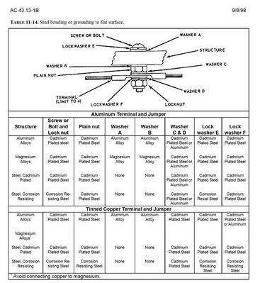 Another builder posted a question about possible corrosion at grounding points, and George McQueen, provided a very useful pointer to the material on this subject in FAA Advisory Circular AC 43-13-1B, Acceptable Methods, Techniques, and Practices - Aircraft Inspection and Repair. I have a copy of this huge bible, a great reference for best practices, but I had missed the section on electrical grounds. AC 43.13-1B suggests to put an aluminum washer between the tinned copper ring terminal and the aluminum airframe. The washer and the airframe are made from the same material, so there won't be any galvanic corrosion at that interface. The corrosion, if any, will occur between the aluminum washer and the tinned copper ring terminal. But the washer is replaceable, so corrosion there is fixable.
I ordered some aluminum washers, and they arrived earlier this week. I corrected the ground connections to the airframe.
Pitch Axis Autopilot - Research
- Details
- Written by Kevin Horton
- Hits: 4051
I was at a local used computer shop this week, and stumbled across a magazine with a whole bunch of articles on making things with microcontrollers to control them. That got me thinking about my concept of a pitch axis autopilot. I did a bit or research, and determined that while there were dozens of suitable microcontrollers, only the Parallax BASIC Stamp series and the Arduino family have development environments available that run on Mac OS X.
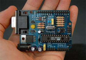 At the moment, the Arduino seems to be the front runner, as it has some features that the BASIC Stamps don't, such as the ability to directly read analog inputs, which could be useful to allow the gains to be varied in flight during development. The Arduino also seems cheaper, as it comes mounted on a circuit board with power supply, input and output connectors, etc, while the board for the BASIC Stamps is extra.
The Arduino microcontroller has an interesting background - it is the product of an open source development effort. In other words, rather than being developed commercially, it was a collaborative design project between a number of amateurs. Despite the humble beginnings, it seems to be quite a capable device, and perhaps because of the open source heritage, it has development environments that run on Windows, Mac OS X and Linux, whereas most other microcontrollers only support Windows.
I've also discovered that there is a plug-in that allows Python to be used to read and write parametres from the X-Plane flight simulator. In theory, that should allow me to trial various control law algorithms quickly at home, and only flight test the ones that look the most promising. I'll attack this after I get flying.
Canopy Handle
- Details
- Written by Kevin Horton
- Hits: 4125
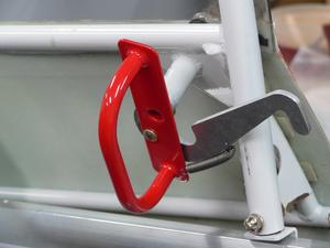 The grey powder coat on the internal canopy release handle had been chipped, allowing a bit of rust to start in one place. I had it sand blasted and powder coated red.
Garmin GNS 430 WAAS Upgrade
- Details
- Written by Kevin Horton
- Hits: 6784
My Garmin GNS 430 came back from its WAAS upgrade on Friday, making it a GNS 430W. I reinstalled it this weekend.
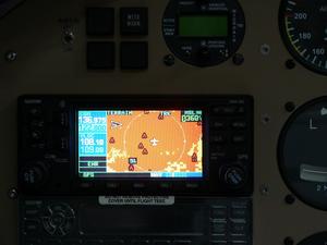 The upgrade also included a new Terrain display, with warnings about terrain that is too close below, or high terrain that is within 60 seconds flying time ahead. It isn't quite a Transport Category Terrain Avoidance Warning System, but it is pretty good, all in all.
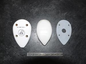 The GNS 430W needs a new antenna, and I was disappointed to see that the new one, although it had the same mounting screw spacing, was wider and longer than the old one. That meant that the spacer I had made to fit between the curved fuselage and the flat antenna bottom was too small. It was a pain in the you know what to make the first spacer, and I didn't want to to invest the time now to make a new one.
The new GA-35 antenna is on the left, the old one in the middle, and the spacer for the old one on the right.
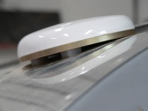 I made some little tapered UHMW plastic spacers to go go over the two outboard screws for now. I'll make a proper spacer sometime after I get flying.
Looking at the Installation Manual for the GNS 430W, it seems that there are several different antennae that could be used. One of them, the A34, supposedly has the same footprint as my original GA 56 antenna. I should have done this research earlier, and specified a requirement for the A34 antenna. I'll call the avionics dealer I use, and see if I can return the GA 35 antenna, and get an A34. That is a more interesting option than making a new spacer.
Small Victories
- Details
- Written by Kevin Horton
- Hits: 4072
This week I did a tiny bit of wiring clean up ahead of the firewall, then bit the bullet and took a closer look at the Hall Effect current sensor. A Hall Effect current sensor is a loop that goes around a conductor, allow the current flowing in the conductor to be measured without physically putting a current sensor in the circuit. I purchased such a sensor from Grand Rapids Technologies to measure the current produced by the main alternator. The current sensor has three long wires attached to it, and I connected those wires to the engine monitor when I did its wiring, being careful to cut them to a length that allowed putting the current sensor loop where I intended to run the alternator cable. But, I later discovered a major interference problem with the planned alternator cable routing, and I moved it to the other side of the engine, without thinking about the impact on the current sensor.
A few months ago I realized that the current sensor was still hanging forlornly from its wires, and the alternator cable was now way over on the other side of the engine. Big depression :( It seemed obvious that the current sensor wires were too short to reach the alternator cable. I was convinced I was going to have to splice the three wires, and I wasn't sure whether that would affect its accuracy or not.
Mid week, I did what I should have done when I first discovered the "problem" - I actually grabbed the Hall Effect sensor, and pulled it over towards the alternator cable. Much to my surprise, I discovered that I actually had just enough length on the wires to get the current sensor around the alternator cable where it made a bit of a loop at its current limiter. That was a very nice surprise. I was very, very happy. I managed to secure the wire on some existing screws, and all I have left to do is find a good way to hold the current sensor in place.
