Pitot Line Snap Bushing Saga
- Details
- Written by Kevin Horton
- Hits: 4337
I got out to the hangar for a few hours on Monday and Wednesday evenings, plus about five hours during the day on Saturday. A big hardware order arrived from Van's on Monday, so I was able to finish off a bunch of items that were 80% complete. I'm trying to keep the number of partially finished tasks to a minimum, to make it easier to keep on top of what needs doing.
I spent quite a bit of time working on the routing for the Nav antenna coax, which goes from the instrument panel, under the floor, then out the right wing to the antenna in the wing tip. For some stupid reason, when I installed the coax in the fuselage, I trimmed it a bit too short. Once I ran it out to the wing tip, I discovered that it was perhaps two inches shorter than it needed to be. It would be a big job to run a new piece of coax from the instrument panel, through the landing gear box, through the wing spar, and under the floor plus I didn't have any more long lengths of coax in stock. So, I had to find another solution. I studied the current routing, and found two places where a simple reroute would shorten the path by a few inches. I managed to gain about three inches at the outboard end, at the expense of two hours of work.
On Saturday, I attacked the pitot line in the left wing. I quickly learned that I should have done this before installing the wings. The first task was to install the plastic snap bushings that go in the holes in the wing ribs, to protect the pitot line from chaffing. I had thought that this would be an easy job, as there are three access covers in the lower wing surface, and there are large lightening holes in each wing rib that make it easy to reach from one wing bay to the next. I discovered that while it was easy to install the snap bushings in the ribs that were right next to an access cover, it was a whole different story once you were reaching through the lightening holes. And, this being a tail dragger, if you drop a snap bushing, it rolls aft towards the rear wing spar. I ended up searching for two dropped bushings with a light and mirror, then fiddling around blind trying to grab them. One of them rolled all the way aft, out of reach. I eventually managed to snag it with a small piece of wood, and coax it forward so I could grab it.
And things got much worse once you considered the wing root area, where there are four wing ribs very close together. I had thought that I would be able to reach in through the lightening holes from the wing root, but the wing mounts so close to the fuselage that there wasn't room for this option. I had to find another way, using only the tools and materials that I had at hand in the hangar. I eventually came up with a Rube Goldberg arrangement of telescoping inspection mirror handle, and two pieces of nylon cord tied together. This complicated arrangement allowed my to slide each snap bushing along a piece of cord that was routed through the hole in the rib. The snap bushing couldn't come off the cord, and the cord helped guide it into position so I could push it into place with a finger. And, to cap it all off, I arranged things so that at the end the string went through all the snap bushings so I could use it to pull the pitot line through the most inboard wing ribs.
Lesson Learned - install any snap bushings in the wing ribs before installing the wings on the aircraft. For bonus points, also install the flexible pitot line through the snap bushings before installing the wings, so all you have to do is get the pitot line from the wing root into the fuselage.
The next hangar visit, I'll work on running the pitot line from where it enters the fuselage all the way to the instrument panel. I'll also work on its connection to the pitot tube.
Golden Hawk Model
- Details
- Written by Kevin Horton
- Hits: 4295
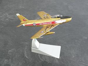 Someone gave me a very nice model of a Canadair Sabre in the Golden Hawks paint scheme. It is autographed by Fern Villeneuve, the first leader of the Hawks. Thank you very much! It is really quite striking, and makes me anxious to get the aircraft painted in that colour scheme. 2009 will be the 50th anniversary of the formation of the Golden Hawks, so I will probably plan to have the aircraft painted next winter.
Running the Wing Wires
- Details
- Written by Kevin Horton
- Hits: 4186
What a winter. The weather office says that since November 20th, when the first big storm hit, there have only been six days when we didn't get any snow. We've had more snow in November and December than in any previous winter since they started keeping records. Saturday morning I helped Ron, the hangar owner, clear the snow between the hangar doors and the taxiway. That was a tiring job.
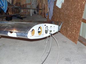 Saturday I revisited the wires going from the fuselage through the left wing. I had successfully run the pitot heat, landing light and nav light wires during my last work session, but the strobe power cable had been giving me fits. I could pull it part way through the conduit, then it would get hung up on something. I tried three times, and it stopped at the same place every time. I got so frustrated that I put that job aside for another day. Saturday I took a fresh look at things, and quickly found the problem - somehow the nylon cord that I was using to pull wires through the wings had gotten wrapped around the landing light wire. I sorted that out, and then it was a quick job to pull the strobe power cable and COM 2 antenna coax through.
I'll have a Bob Archer antenna in each wing tip - the COM 2 antenna is in the left wing tip, and the NAV antenna is in the right wing tip. Many people are using the Archer wing tip NAV antenna, and report that it works extremely well (see Sam Buchanan's report). You would naturally expect that there would be a dead zone in the antenna reception on the side of the aircraft opposite the antenna, but users report that they can't find a blind spot. I'm looking forward to seeing for myself. The GPS in the GNS 430 will be my primary navigation source, so even if there is a small dead zone, it won't be critical.
The wing tip COM antenna gets more mixed reports. Some people report very good performance, and some are not happy. The wing tip is a more difficult place to mount a COM antenna, as COM signals are vertically polarized, and the antenna needs some vertical development. There are only about 8 inches of vertical room inside the wing tip, which is pretty marginal. If need be, I'll mount a second COM antenna on the belly.
There will be periodic blasts of high voltage energy going down the strobe power cables. It is a shielded cable, and the antenna coax is also shielded, so in theory there shouldn't be a problem of strobe noise making it into the COM and NAV antenna signals. But, just in case there are some imperfections in the strobe cable, antenna coax, or the theory, I ran the strobe cable and antenna coax in separate conduit about 12" apart.
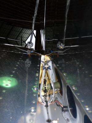 Here you see the root of the left wing, on the left side of the picture, and its reflection on the fuselage side skin on the right side of the picture.
I secured the bunch strobe cable and the wires going to the upper conduit to the fuselage side with an Adel clamp, to ensure that they couldn't foul the aileron pushrod.
When mounting the wings, I discovered that there was a wiring bundle just aft of the lower wing bolts on each side, and that the wing bolts fouled these bundles when trying to put them in the holes. I had to remove the Adel clamp that secured each bundle to the fuselage side below the aileron pushrod so I could move the bundles out of the way to allow the lower wing bolts to be inserted. The access to the outside of the fuselage was extremely poor in this area, as there was very little room between the wing root and fuselage side, and the lower fuselage skin extended outboard to the wing surface, preventing access from the bottom. I was afraid that getting those Adel clamps back in place would be an impossible task.
Saturday I decided to have a go at resecuring those Adel clamps. I got very lucky, and managed to get the nuts on the screws by taping an 11/32" wrench to a long wrench so I could reach the screw hole from the upper wing surface, taping the nut in place in the wrench, fitting the nut over the end of the screw, then taping the wrench in place on the fuselage side to hold the nut in position, and finally climbing in the fuselage to turn the screw. I couldn't believe my luck when each screw quickly threaded into the nut.'
The five wires and cables for the left wing are all in place, and two of the four for the right wing are done. The next trip to the hangar I'll work on the remaining two on the right wing, and secure the bunch of them to the fuselage. Then I'll work on connecting them to their services in the wing or wing tips.
Slow Progress
- Details
- Written by Kevin Horton
- Hits: 3411
Progress the last two weeks has been frustratingly slow. We had several snow storms that meant that the taxiway to the hangar would be impassable. I had some Christmas shopping to do, and a couple of otherwise good evenings were eaten up with a work trip to Montreal. And we had family in town the last ten days, which occupied a bunch of time.
I did manage to get the wing bolts torqued, but that took much more time than expected. The upper bolts were a piece of cake, but it took a lot of fiddling around to find a workable combination of sockets, extensions and wrenches to get at the nuts on the lower bolts. The nuts are self-locking, so you can't just spin then down with your fingers. There wasn't good access to get a socket on the lower ones, as the cockpit floor slopes upward in front of the nuts. And the landing gear box braces hindered access with a wrench, only allowing about 30 degrees of motion on each swing of the wrench. So it took a fair bit of time just getting the eight lower nuts on to the point where a torque wrench was needed. The right side was especially bad, as I had put the wing leveler servo a bit too close to the spar. Suffice it to say that the imagined quick job of torquing the bolts turned into several hours of work.
I attacked a whole bunch of other small tasks, but kept on finding that some critical part or tool was still home, or that I needed to order some little bolt. Every trip to the hangar I take more aircraft parts and tools - eventually everything will be there. I put one hardware order in to Van's, and I'll need to do another order soon. I did manage to get the wiring to the elevator trim servo hooked up, I started hooking up the aileron pushrod at the stick, but found that I needed to order longer bolts. Same problem with the elevator pushrod. I reinstalled the last of the brake lines (I had removed the portion on the aft side of landing gear legs, as I was afraid that they might get damaged when pushing the aircraft up the ramps onto the trailer).
I ovaled the holes for the GPS antenna, to move it a bit further away from the canopy rail on the rear fuselage. I came up with a way to secure the extra four feet of antenna coax that the GNS 430 WAAS upgrade required, but I need to order some hardware to implement the idea. I started running the various wires and coax cables from the fuselage to the wings.
Tomorrow is my last day off before heading back to work. I had hoped to spend the day at the hangar, but we got a big dump of snow today, and I fear that the taxiway will be impassable.
Slow, Cold Progress
- Details
- Written by Kevin Horton
- Hits: 3651
I was in Wichita from Sunday to Thursday, so didn't get make any RV-8 progress until this weekend. I had planned to go to the hangar on Sunday, as the temperature was forecast to be quite a bit warmer than on Saturday. But then a big winter storm developed, that was expected to yield "blizzard-like" conditions on Sunday, so it was Saturday or bust.
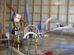 Saturday morning the temperature was -22°C (-8°F), which seemed a bit cold to be trying to work on the aircraft, so I delayed my departure until after lunch, when it had warmed up to -18°C (0°F). It was decidedly frigid in the hangar, but thanks to a sweater, winter jacket, insulated pants, insulated boots, thick toque, warm gloves, and a radiant heater pointing into the cockpit, it wasn't too bad. I managed to get about three hours of work in before the cold started to get too me. I tapped the 7/16" wing bolts the rest of the way home, installed the remaining 1/4" wing bolts (expect for one that had a strange gouge with corrosion in the gouge), and snugged up all the nuts on those bolts. I had hoped to get at least some of them torqued, but things went fairly slowly working in all those winter clothes.
One of the reasons I wanted to work in the hangar yesterday was to see whether it was practical to make any progress when it was quite cold. It was -18°C in the hangar when I started, and -16°C when I finished. It wasn't too bad, so there is some hope that I'll be able to make progress most weeks this winter.
It is snowing like crazy today, so needless to say I didn't go to the hangar. It will probably be a few days before the snow is cleared from the airfield, so I probably won't get back out there until Tuesday or Wednesday.
Wings Mounted
- Details
- Written by Kevin Horton
- Hits: 3793
This morning Jim MacLachlan (purchased partially completed RV-7A kit), Mark Richardson (built RV-8), Michel Asselin (building RV-7A) and Lee Fasken (purchased a share in an RV-6) came by the hangar to help me mount the wings. It went quite quickly, with one guy supporting the wing tip, two at the wing root (one at the leading edge, and one at the trailing edge), myself guiding the main spar into the slot, and the last guy keeping an eye open for problems. Once the wing spar was inserted, I clambered into the cockpit with a light and mirror to peer through the 7/16 bolt holes in the spar to give verbal directions to get them lined up, then I slipped two tapered drift pins in place - one in an upper bolt hole, and one in a lower bolt hole. Then I took the lubricated close tolerance bolts, and slipped them in place while turning them with a ratchet. They could be pushed about 2/3 of the way in while turning them, and the last 1/3 was accomplished with some gentle taps with a hammer, with a piece of wood between the hammer and the bolt head.
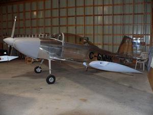 All the 7/16" bolts are inserted, but I didn't insert all the 1/4" bolts, nor did I torque the bolts yet, as I didn't have a lot of time. After both wings were on, I installed the left wing tip (three screws only), the left flap, left wing intersection fairing and the empennage fairing.
 Then I took a picture that goes with the Application for Certificate of Registration. I realized that I had forgotten to bring the nav and strobe lights, the cover that goes over those lights, the landing light cover and the rudder bottom. I decided to arrange the "official" picture so the end of the wing tip was blocked by the wing tip of one of the Mooneys that are in the hangar.
However, Terry convinced me that I shouldn't send in the C of R application with this picture. She is afraid that the bureaucrats might throw the application back, complaining about the partially blocked picture, and that this might delay things by several weeks. It would be better to delay things by a few days so I can take a proper picture, with all the missing items installed.
