Fuel Tank Service Bulletin
- Details
- Written by Kevin Horton
- Hits: 4856
There have been at least three engine failures caused by fuel pickup tubes that came loose inside fuel tanks. One aircraft was destroyed in a forced landing (the pilot survived, fortunately) and at least two other aircraft did successful forced landings. In February, Van's released a Service Bulletin (SB) on the subject. The SB calls for the tank access covers to be removed, the fuel pickup tube fittings to be drilled for safety wire, tightened, and safety wired.
It seems that two of the three incidents were on aircraft that had been built from quick build kits. The builder does not build the fuel tanks on these kits - he just has to inspect them, then install the access cover. The fuel pickup tube is in place, but not tightened. It seems that many builders miss the step in the instructions where they are told to tighten the fuel pickup tube.
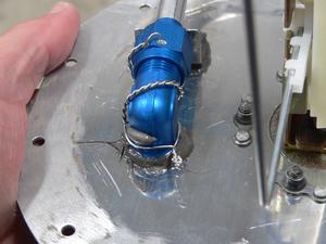 I was reasonably sure that my fuel pickups were tight, but decided to open the tanks up just to be safe. It took several hours work to get the access covers off and clean the old Proseal off. I drilled the fitting the for the fuel pickup on the right tank and secured it with safety wire.
The left tank has a flop tube (fuel pickup on the end of a flexible hose) to provide fuel during inverted flight. The SB calls for the flop tube to be safety wired to its attachment elbow fitting. I wasn't crazy about this, as it means you have to pull the attachment elbow out of the tank so you can so the safety wiring. Then you have to Proseal it back in place and hope it doesn't leak. And, you have to do this all over again whenever you replace the flop tube (they gradually stiffen up as the hose ages).
Having a flop tube come loose doesn't really add a new risk, as flop tubes can get hung up inside the tank so that they aren't resting on the bottom. The result is the same in either case - a bunch of fuel in that tank becomes unusable. So, if you have a flop tube, you need to always operate the aircraft as if fuel in that tank may not all be available. In other words, you plan to use the fuel in that tank first, so that if it all doesn't feed you can switch to the other tank and land.
Given that having a flop tube come loose is no worse than having it hang up, which is a risk that I have already accepted, I decided to not put safety wire on the flop tube. I simply made sure it was very tight, and then put some Proseal between the fitting and the threads. The Proseal will be almost as good as safety wire, but it won't make it too much harder to replace the flop tube when that time comes.
 For some reason, I thought I should check the resistance of the fuel senders while I was working on the tanks. This turned out to be a good idea, as the one on the right tank gave screwy results. It turned out that the fuel sender was not grounded to the tank - the Proseal acted as an insulator. I'm glad I discovered this now, as I would have needed to mix up some more Proseal whenever I found the problem. I fixed it by removing one of the fuel sender attachment screws, and put a ring terminal on it, with internal tooth lock washers above and below the ring terminal. The teeth on the lock washers made a good connection between the fuel sender and the attachment bolt, and now it seems that the attachment bolt has a good connection to the tank. Now the fuel sender resistance is correct, even without hooking up that ground wire.
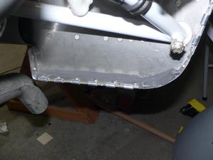 I had some left over Proseal, so I used it to seal the bottom corners of the firewall. I wish I had done that a long time ago, as I spilled some oil when I pulled one of the oil hoses off to pressure test it. The spilled oil ran down the firewall, and some of it seeped inside the lower fuselage. The oil later seeped out near the right landing gear leg area. The spilled oil is inside the lower fuselage, where I can't get at it. It will probably cause untold grief when it comes time to paint the aircraft.
Plenum Chamber Fabrication 4
- Details
- Written by Kevin Horton
- Hits: 7151
Plan A for the transition piece between the upper cowling and the plenum chamber didn't work out. Last Sunday night I hardly slept, as I kept waking up with new ideas on how to make this work. I would ponder each idea for awhile, consider its pros and cons, and then fall asleep for a while. By morning I had the germ of Plan B.
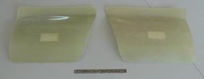 Plan B - I remembered that if you use standard cooling baffles, Van provides two curved pieces of fibreglas to be grafted on to the upper cowling inlets. These pieces provide a smooth upper guide for the air as it comes in the inlet and expands into the area above the engine.
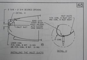 Here you can see the section of the plans that show the inlet ducts, if you use standard baffles.
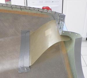 I temporarily clecoed and taped the fibreglas pieces in place (view of upper cowling, upside down).
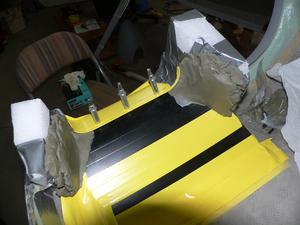 I covered the fibreglas with vinyl tape, and used Styrofoam and modelling clay to form a mold for the sides of the right transition piece.
If the right side shows that this plan will work, then I will make another one for the left side.
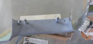 I will rivet a piece of aluminum to the upper cowling.
The fibreglas transition piece will be attached to that piece of aluminum with three screws and nutplates. There will be a piece of rubber from a tire inner tube that will go between the transition piece and the plenum chamber, to form an air tight, but flexible seal.
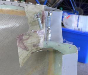 Side view of transition piece clecoed in place.
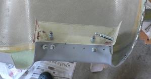 Top view of transition piece clecoed in place. The contour on the inner edge (left side of the picture) didn't come out quite right. It ends up too far away from the front wall of the baffles. I've cut it off, and tonight I grafted a new section on. Hopefully this will be better.
Misc Update
- Details
- Written by Kevin Horton
- Hits: 3399
It's been a crazy week, and I needed to do some yard work to get ready for fall. As a result I only got a bit of time on the project. I did get the alternator bracket torqued and safety wired. I can't believe how long that took - it is in a pretty crowded area (I could have removed the induction air snorkel), so it took me three attempts to get it done properly.
I also finished the riveting on the forward baffle wall, but even that was a struggle. I had that thing together several times, only to see a problem that needed fixing, which meant disassembling it again. One of those five steps forward, four steps back kind of things, but at least it was positive progress.
Today I had a go at making a metal piece that was intended to make a stepped flange that the eventual fibreglas transition piece will be attached to. But, I put the cowling on, with the metal piece clecoed in place, and it is obvious that this plan isn't acceptable. I would need some very sharp angles to transition from the metal flange on the cowling to the fibreglas transition piece, and that would be too draggy. I need to do some head scratching to come up with a better plan.
I've got tomorrow off. I had planned to make the fibreglas transition pieces for the plenum. But, now that I've run into a glitch with Plan A, I'll do some of the other items on the list instead.
B&C Specialty Alternator
- Details
- Written by Kevin Horton
- Hits: 4649
I was planning to use an alternator that I had purchased from Mark L, an RV-4 builder. Mark modifies automotive ND alternators to allow them to be used with an external regulator. But, I've reconsidered that plan, as I've seen too many reports from people who have experienced alternator failure. This is one of the most common failures. An alternator failure wouldn't be a safety issue, as I have an 8 amp standby alternator that will allow me to power the essential items indefinitely. But, I plan to do a lot of travelling with the aircraft, and an alternator failure while on the road would be a major hassle. It wouldn't be easy to purchase a drop-in replacement alternator, as a standard automotive alternator is designed to use its internal voltage regulation, and my wiring system is setup for an external voltage regulator. And I can't count on getting an identical unit from Mark L., as he basically modifies whatever ND alternators he can find.
B&C Specialty also sells modified automotive alternators. But they do things like install better quality bearings, and balance the rotating components. They have sold thousands of alternators, and the failure rate is supposedly pretty close to zero. And, if I ever do need a new one, I can get it shipped the same day. Their alternators are much more expensive than the one I already had, but I figure it is worth it to get better reliability, and a quicker replacement, if I ever need it.
MY 60 amp B&C Specialty alternator arrived last week. I'll work on installing it soon.
Plenum Chamber Fabrication 3
- Details
- Written by Kevin Horton
- Hits: 4949
This last week I the mating surfaces of the plenum chamber cover, then riveted the cover together. Then I disassembled most of the vertical pieces of the baffling, primed the mating surfaces, and riveted those together. The basic baffle plans have the whole baffle assembly riveted together, which means that it is impossible to remove from the engine without drilling out a bunch of rivets. I decided to use screws and nutplates in strategic locations so the baffles can be installed and removed in sections.
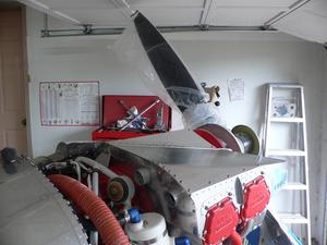 This afternoon I reinstalled the baffling and did a trial fit of the cover. So far so good. I primed the mating surfaces on the front baffle pieces. Tomorrow I'll rivet those together and install them. Then I'll attach the fibreglas transition pieces that go from the cowling to the plenum chamber cover.
Plenum Chamber Fabrication 2
- Details
- Written by Kevin Horton
- Hits: 5280
I was on the road for a couple of days this week, but I did make good progress on the plenum chamber cover. I had thought I would need to make it in many pieces, but ended up getting away with three large pieces, plus two long transition pieces that go at the joints.
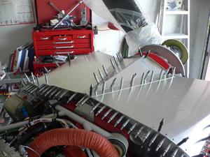 Today I finished the trimming and most of the drilling of the cover, except at the very front. I need to sort out how far forward the metal will extend before I trim and drill the front. I've got to decide on the screw spacing before I drill a few more holes along some of the long straight edges. Next I'll order a bunch of nutplates, and prime and rivet the pieces together.
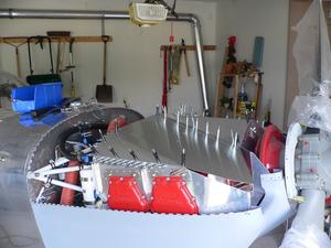 Next, I've got to fabricate short fibreglas transition pieces that will attach to the cowl inlets. These transition pieces will be attached to the plenum with a piece of rubber, to allow for the relative motion between the engine and cowling.
