More Fibreglas
- Details
- Written by Kevin Horton
- Hits: 3570
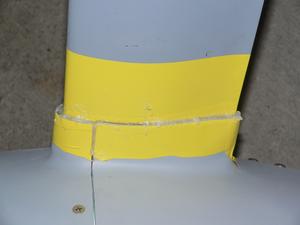
I had thought I was getting close to the end of the fibreglas saga, then I remembered the wing tips, which were sitting in the basement. I had done most of the fibreglas work on them, but I knew that I wasn't finished. A quick look at them showed that they had gotten all scratched up somehow, and that there were some areas on one tip where I had not finished adding filler. :( I started working on them again a few days ago. One tip doesn't quite match up with the outboard end of the aileron (I already knew that). I'm going to look at other RVs at Oshkosh, to see how noticeable that type of flaw is on a finished aircraft. Maybe I'll just ignore this one.
I had used the fuzzy side of Velcro to fill some gaps beneath one of the upper landing gear leg fairings and a wheel pant to gear leg fairing junction. I had hoped that this would be an acceptable solution, but it was too visually prominent. The white Velcro was very noticeable. Black, the only other colour I've seen, would be equally visible. I would need gold coloured Velcro.
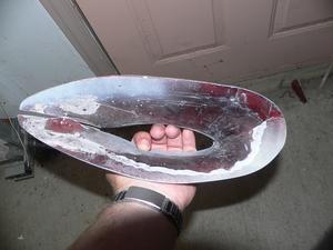 I decided to try a proper fix. I put some 3M 471 vinyl tape on the fuselage and landing gear fairing, then mixed up some fibreglas resin with micro-fibres. I put the goop under the edge of the fairing and screwed it in place. I popped it off a couple of days ago, and cleaned up the edges. I've got a perfect fit now.
You can see the added filler on the bottom and right side of the picture.
Dynon Firmware Update
- Details
- Written by Kevin Horton
- Hits: 3942
Dynon has just released a firmware update for the EFIS-D100, EFIS-D10A, EMS-D120, EMS-D10, and FlightDEK-D180. The biggest change is a new round DG option - either full screen on the D-10A, or split screen on the D-100.
There is a thread on their support forum for questions.
Oshkosh
- Details
- Written by Kevin Horton
- Hits: 3322
I hope to be at the EAA Fly-In at Oshkosh this year. John, a co-worker, has a Cessna 172 - he has been interested in going to Oshkosh for years, but has never made it. We hope to arrive on Saturday, 22 July, weather permitting. I don't know how many days we'll be there, as the weather will drive our schedule.
I hope to make it to Bob Collins' RV BBQ, and we will also try to organize some sort of RV-8/8A builder get-together.
Rudder Bottom Fairing
- Details
- Written by Kevin Horton
- Hits: 8072
I've had two visits from RV-7 builders in the last few weeks - Chris Cox from Vancouver, and Alexandre Menezes from Brazil. Chris also works for Transport Canada, and we met through another TC RV builder. Chris is getting ready to start his electrical system, and is somewhat spooked by it. He was in town for a meeting, so came by to see how not to do an electrical system :). Alex somehow found my web page from Brazil, and stopped by as he is in Ottawa for a few months. He built the first RV-7 in Brazil.
I've been making slow, steady progress the last few weeks. I had fallen off the step in terms of hours spent in the garage, so I've been slowly working the pace back up. I've gotten bogged down in fibreglas work, which I don't enjoy, so that has sapped my motivation. But I am getting closer to the end there, so I think I can see the light at the end of the fibreglas tunnel.
I've crossed a small number of things off the snag list, but I've found many new issues to sort out. In the old days, I would simply add it to the snag list, and forget about it. Now I try to close off issues as soon as I find them.
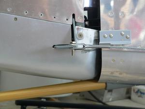 I decided to start at the tail, and work forward, looking for things that needed doing. The first item that caught my eye was the rudder bottom fairing. I had gotten the main part of it done a long time ago, but I had never finished the little removable part at the front. The fairing comes in one piece, but there is no way to fit it around the rudder horn without cutting it in two pieces. I decided to cut slits in the main part, so it would fit over the rudder horn when pushed forward, and to make the top forward part removable. I even made a neat tab that held the front part in place at the centre. It was a work of art, but my idea for running the nav/strobe light cable didn't work out, so the idea blew up.
I had planned to run the cable up the aft side of the vertical stabilizer spar, then bring it down into the rudder bottom fairing. But there wasn't enough clearance between the front to the rudder bottom fairing and the spar for the cable. So, I needed to cut a large hole in the front of the rudder fairing to run the cable through, which interfered with my nifty locating tab. I hacked the tab off, and found that I didn't really need it.
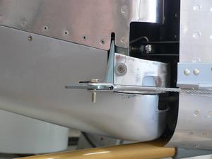 Here is a view with the rudder pushed hard left. You can see where I had to hack some divots out of the removable part to clear the bolt heads that hold the VS spar to the fuselage.
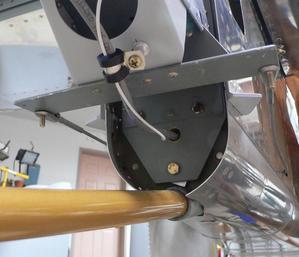 I ran the nav/strobe cable through the VS spar just below the lower hinge bracket.
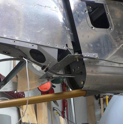 I used an Adel clamp on a stand-off to hold the cable in place to the bottom of the rudder. That ensures that it doesn't rub against the top or bottom of the slot in the fibreglas.
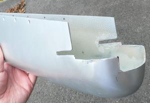 Here you can see what the front of the main part of the bottom rudder fairing looks like.
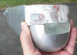 Here is a show showing how the removable part fits. The nav/strobe cable goes through the slot between the two pieces of fibreglas.
Upper Landing Gear Leg Fairings
- Details
- Written by Kevin Horton
- Hits: 5291
I've had a very busy few weeks, so project essentially stopped for about a month. But I got back at it about 10 days ago, and have been beavering away on finishing the upper gear leg fairings and the wheel pants. I started the landing gear fairings months ago, but am finally getting near the end.
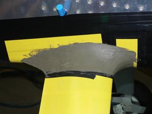 I made the upper gear leg fairings by putting vinyl tape on everything, putting oil based modeling clay in place to make the shape, then laying up some fibreglas over it. I slit the back to get it off.
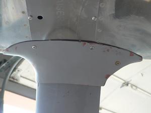 I used two existing screws to hold the bottom of the fairing to the bottom of the fuselage. I used a screw at the back to hold the fairing tightly together at the split line.
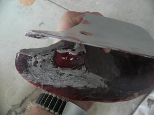 The screw at the back goes up from the bottom, so it won't be visible unless you look under the fuselage. It screws into a nut plate that is fibreglassed inside the fairing.
 I don't think I'll need any screws on the top side, as the fairing sits quite tightly against the fuselage. I had a tiny gap at the front of one fairing, but I put the soft side of some Velcro on the inside of the fairing to take up the gap. This will also keep the fairing from scuffing the paint, I think.
You can see a hole at the back where I had to drill to make a recess for the threaded part of the nut plate to go into. That hole will be filled in with fibreglas filler, so it won't be visible once everything is finished.
Oh My Aching Back
- Details
- Written by Kevin Horton
- Hits: 4549
I saw a thread on the VAF WWW forums awhile ago about a clearance problem between wheel pants and brake calipers. I put an item on my To Do list to check this. I've been working on the final wheel pant tweaking lately, so yesterday I finally screwed up the courage to take a look at this on the left wheel pant. Sure enough, the back bottom corner of the brake caliper was hitting the wheel pant. This would push the floating caliper towards the brake disk, causing a dragging brake. At best, this would only lead to excessive brake wear. At worst it could lead to overheating brakes and a brake fire, or a control problem on the ground.
Some guys said they fixed the problem by putting a bulge in the wheel pant in this area. That would certainly work, but the thought of even more fibreglas work turned my stomach. Some other people reported that they fixed the problem by bending the wheel pant attachment bracket to push the bottom part of the wheel pant inboard, away from the brake caliper. I decided to try this.
I spent two hours tonight bending the bracket a bit, then putting the wheel pants on (one hard to get at bolt on the axle, plus a whole bunch of screws), using a flashlight and mirror to check the clearance, only to see that the wheel pant still hit the caliper, taking the wheel pant off, and then repeating the process. I finally got just the right bend on the bracket so I have about 0.050 inch clearance (as judged by a finally calibrated eyeball).
My back is very tired after two hours on my knees, bent over that wheel pant, so I am having a very tasty beer.
Update - 22 Jun 06 - I checked the right wheel pant this evening, and it too was hitting the brake caliper. I tweaked the attachment bracket to solve the problem. It went a lot quicker than last night, as I had learned a few things.
The big lesson is to be careful to keep the same angle on the flat part of the bracket that the wheel pant mates up to. Last night, I started off only bending the bracket right where it comes off the landing gear leg. This moved the end of the bracket inboard, which is what I wanted, but it also changed the angle on the end of the bracket. Then, everything would look OK until I tightened the screws that held the wheel pant to the bracket. As soon as I tightened the screws, the wheel pant would deform and hit the brake caliper. I finally figured out that I needed to bend the bracket in two places - at the landing gear leg, and at the flat part where the wheel pant attaches. The bracket needs to be parallel to the wheel pant surface, so that the wheel pant doesn't deform when you tighten the screws.
