Front Cockpit Fresh Air Vent
- Details
- Written by Kevin Horton
- Hits: 5467
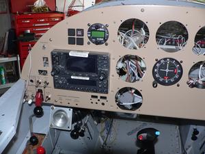
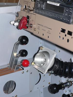
I decided to install the front cockpit fresh air vent a few days ago, as it is on the list of things to finish before I rivet the last skin in place, and it looked like a quick task. Most builders put that vent in the lower left corner of the instrument panel. I had originally planned to put mine there, but eventually decided to use that space for switches. The main switches are on a switch console on the right side of cockpit, but there wasn't enough room there for all the switches, plus I'll have my right hand on the stick, so it made sense to put switches to be used in flight on the left side. I decided to put the fresh air vent on a bracket attached to the bottom of the instrument panel, way over on the left side.
I fabricated the bracket a few days ago, bolted the vent to it, then clamped the assembly in place to confirm this was a good location. I had made the decision to put the vent there over three years ago. In the meantime I had installed the throttle quadrant, which mounts on the left side of the cockpit, below the instrument panel. After clamping the vent in place, I made the distressing discovery that it was too close to the throttle quadrant - the prop and mixture levers would hit the vent before they reached full travel forward. I tried moving the vent a bit to the right to get it away from the throttle quadrant, but now the stick grip came very close to it if the stick was put in the forward left corner - I could easily hit my hand on the vent. Plus it looked like it might be too close to my left leg. Arrgh!!
I needed to find Plan C. I put the cockpit floors and front seat in, so I could sit in the cockpit and study things from the best perspective. I looked at several other places to mount the vent, but they all had some problem - either my left leg would hit it, or it was too low, or the airflow would be blocked by something, or there would be no good way to route the duct carrying the fresh air. The only good option I could find was to put it on the main instrument panel, below the CDI in the centre of the panel. This would give a good shot to flow fresh air in my face, but it would look very strange, and it would preclude me ever adding anything else to the instrument panel in that spot.
 Finally I hit upon the idea of making a bracket to mount it above the inboard side of the throttle quadrant. This makes room for my hand on the throttle quadrant, it is clear of my left leg, and I managed to orient it so it can blow directly at my face. It did partially block the access to the Alternate Air control, which was a problem as this is a control to be used in an emergency, so it needs to be easily seen. I ended up moving the Alternate Air control below the Oil Cooler Door control.
 I've just got temporary bolts securing the vent to the bracket now. I've got four round head screws on order, as they'll look better.
Forward Fuselage Update
- Details
- Written by Kevin Horton
- Hits: 4931
I've been working away to finish off anything in the forward fuselage that will be easier to do with the upper forward skin removed. I thought there were only two or three such tasks, but I took a good hard look at the whole area and came up with 13 items that I should do before riveting that skin on. I got four items finished, then found one more. So, that makes 10 items to go.
One of the items on the list was to confirm that I had the EIS 4000 Engine Monitor tachometer input wired correctly. I'm not sure why I was suspicious about that one, but something was bothering me, so I checked it out. Sure enough, something didn't make sense when I used an ohmmeter to check out the wiring. It took about three hours of puzzling around, studying wiring diagrams, and Googling to figure out how magnetos worked, to learn that the ohmmeter readings were normal, but there was a missing resistor in my tach wiring. Once I knew what I was supposed to do it only took a half-hour to put it right. I'm glad I noticed this now.
I decided to put some acoustic and thermal insulation on the cockpit side of the firewall, to try to keep it quieter and cooler in the cockpit. I ordered some stuff from an aviation supplier that was marketed for this function. It arrived earlier in the week and I started installing it. I'll use adhesive backed Velcro to hold it in place - that will let me remove it if required to inspect the underlying structure. I was about half-way through the installation when I decided to see how this stuff reacted to a flame. I took a scrap of it, and fired up a propane torch. I was quite dismayed to see that this stuff would burn, producing thick black smoke. The fire would eventually self-extinguish if I removed the flame from the torch, but I'm now a bit unsure whether this stuff really belongs in an aircraft. I'll talk to a couple of the Occupant Safety engineers at work to learn more about the testing that materials to go in type certificated aircraft are subjected to, and what type of insulation materials are best. I won't mention the type of material and vendor until I learn more about whether it is suitable for aviation use.
I stopped installing the insulation, and just made paper patterns for the areas it will go. It won't be difficult to install later, if I have a pattern to use when I cut it.
I haven't got too much done this weekend, due to various jobs around the house, and a few hours spent at the Ottawa International Jazz Festival.
Annunciator Lights, Alternator Load Meter, etc.
- Details
- Written by Kevin Horton
- Hits: 3749
Earlier in the week I put the final holes in the spinner spacers. Today I took a closer look at them and decided that I didn't have enough of a gap between the prop blade shanks and the spacers. I don't want to chance having the spinner move a bit and ding the prop, so I opened up the gap to 3/32". I primed the inside of the spacers, and I'll rivet them in place sometime this week.
The 14v bulbs for the annunciator lights finally arrived. Dave B., an RV-6 builder, read that I was hoping to find something other than 28v bulbs. He apparently has something to do with light bulbs at work, so he was able to point me at a place in Canada that carried the bulbs I needed. It took forever for them to arrive (mind you, I did opt for cheap shipping, rather than quick), but they are exactly what I needed. I installed them in the panel earlier in the week and did quite a bit of messing around in the dark one evening with a potentiometer in the loop to see what voltage I need for night operation. I eventually decided that I should run them at 7-8v in the DIM setting. They will be running off my Essential Bus, which gets fed through a diode with a 0.75v drop. So, I bought a 5v zener diode, and sometime this week I'll work to wire it up to the dimmer switch.
Thanks Dave! I really appreciated the assistance.
I expected that it would be a quick job to connect the alternator load meter wires to the engine monitor. Thoughts like that are the kiss of death. When I looked at the engine monitor wiring I realized that I had already used the 4.8v power that the load meter Hall effect sensor needed. It was used to power the fuel pressure sender, and it was buried in a wire bundle. It took about two hours to open up the wire bundle, spice into the 4.8v wire, and hook up the three wires for the load meter. I should have thought ahead a bit when I put in the fuel pressure sender. This time I left a loose 4.8v wire, coiled up and labeled just in case I need another power supply later.
To further complicate life, it turns out I need to upgrade the software in my engine monitor to have the alternator load meter read over 50a. Hopefully there is a way for me to upgrade the software, rather than having to ship it back to Grand Rapids.
I'm slowly working down the list of things to do before I can rivet on the upper forward fuselage skin. The Ottawa Jazz Festival is coming up, and we'll probably spend much of the next two weekends there. But, hopefully soon after that I'll be able to rivet on that skin.
Spinner Spacers
- Details
- Written by Kevin Horton
- Hits: 3403
This week I sorted out where the alternator load meter Hall effect sensor will be mounted, and strung its wires from there to inside the cockpit. The wires are just hanging loose for now - I still need to secure the sensor and wires, and run them into the engine monitor connector.
I haven't made as much progress as I would have liked lately, as I've been trying to work on stuff I don't enjoy. So I decided to take a step back, and try a different task - the spinner. I had done the majority of the work on the spinner many months ago, but there were still several aspects that needed to be finished. I drilled all the holes for the platenuts that the spinner attachment screws go into, primed the forward bulkhead, and rivet all 20 platenuts in place.
 Then I attacked the spacers that fill in the gap between the back of the propellor blade shanks and the spinner rear bulkhead. I had made 0.032 templates for those gaps before, but I had never made the final 0.062 pieces. It sure was a bear putting a curve in those 0.062 pieces :(. The plans show riveted on tabs that secure the forward ends of the spacer to the spinner. They didn't look that important, and a bit finicky to make, so I almost skipped them. But, I decided to calculate what the forces were on the ends of the spacers - I just about died when I calculated that they are subjected to an acceleration of over 1,200 g when the engine is turning at 2,700 rpm. That would probably be enough to force the ends of the spacer outwards, where it could be caught by the air. So, I made the tabs. I primed the surfaces of the tabs and spacers that will be riveted together, and tomorrow I'll rivet the tabs to the spacers, and drill the holes from the spinner into the tabs so I can fit the platenuts on the tabs.
RV Fly-In, Alternator Installation
- Details
- Written by Kevin Horton
- Hits: 3690
I riveted the oil cooler door bellcrank earlier in the week, then had a few frustrating days when nothing I touched worked out well. I always managed to stop before destroying anything, but some nights you just have to pack it in.
Saturday I went to an RV Fly-In at Smiths Falls (CYSH). It was a beautiful day, warm, with blue skies, and I thought that this weather extended for a long way around. So I expected a good turn-out of RVs. But apparently there were low ceilings or poor visibilities in the rest of southern Ontario, so many RVers who had planned to come had to stay home. There were several RV-8s, including Don Kugler's, who flew up from NJ, and Paul Bailey's eye-catching RV-8A. I took my camera, but never thought to take any pictures. The hot sun addled my brains I guess.
Thanks to Cathy and Dale Lamport for organizing the RV Fly-in.
I'm in the mode of trying to get all the cockpit stuff done, so I can rivet on the skin from the instrument panel to the firewall. One of the last items I need to do is to install the Hall effect alternator load meter, as its wires have to come into the cockpit. That means I need to first install the alternator output cable, which means I need to install the alternator. I expected that this would be quick, as I had sorted out the alternator installation a long time ago, then put it on the shelf. I just had to bolt it in place, and fabricate and install its output cable. Piece of cake.
Not so fast... I had installed most of the engine cooling baffling since I had sorted out the alternator installation. I discovered that I couldn't get the alternator installed, as it's tension arm interfered with the baffle front shelf. I removed the baffle front shelf, installed the alternator, then trimmed the baffle front shelf a bit and tried to reinstall it. It still interfered. I couldn't get the shelf completely in place, so it was hard to see exactly how much I needed to trim it. I ended up in a multi-hour cycle of trim, try to install, trim some more. I eventually decided to rework an attachment bracket that goes between the front shelf and the front wall in the center. This allowed me to do some major surgery on the front shelf, so it now fits - finally.
So, I spent many hours in the garage working, and got a lot done, but it was on a task that I didn't even know I needed to do. So I didn't manage to cross anything off my long mental list of tasks to complete. Depending on your perspective, I either made good progress, or no progress at all this weekend. It all depends on whether you are a "the glass is half full" or "the glass is half empty" type of person. I'm an engineer, so for me the glass is at its design capacity, with a factor of safety of 2.0. :)
Oil Cooler Door - Working
- Details
- Written by Kevin Horton
- Hits: 4600
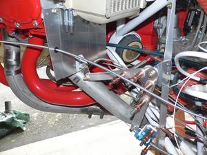
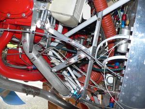
I thought I had a good wooden prototype bellcrank for the oil cooler door control last weekend. But when I took a look at where I would have to bring the Bowden cable through the firewall, I noticed that there was already a bundle of engine wiring coming through there. I couldn't move that bundle anywhere else without cutting a number of EGT probe wires, and the linkage geometry didn't allow me to bring the Bowden cable through anywhere else.
 So, after much head scratching, I changed the linkage design, so that the Bowden cable was no longer anchored at the firewall. This gave me some flexibility in where it came through the firewall. But, the new design had some other issues, so I moved onto version 3. That version was better, but it still didn't solve all the problems. Version 4 looked good, so yesterday I made an aluminum version. Today I drilled the holes in the pivot support, so I could clamp it to the engine mount tubes. I messed up one of the hole locations slightly, which moved the pivot point, which meant I had to shorten one of the bellcrank arms. But it worked.
 Tonight I primed the parts. I have to rivet them together, rivet the Bowden cable attachment bracket to the landing gear box in the cockpit area, put a fire guard over the grommet, and secure the Bowden cable. I also need to fabricate a stop to limit the downward travel of the oil cooler door, so it can not hit the exhaust pipe.
I posted some pictures of the oil cooler door many months ago.
