Forward Skin - 99% Complete
- Details
- Written by Kevin Horton
- Hits: 4821
 I did several short riveting sessions this week, to do all the forward skin rivets that I could reach by myself. This morning Jim, a coworker, came over to man the rivet gun so we could get the rivets that I needed help for. There were six rivets that I had expected to do that I wasn't able to get a bucking bar on. So, I will drill the holes out to 1/8" and use CherryMax CR3214-4-4 blind rivets. These rivets have 1/8" diameter bodies, but the heads (and thus the required dimple) are the same size as 3/32" rivets. This is in addition to the ones inside the top of the landing gear boxes, which I had dimpled for 1/8" CR3212-4-4 CherryMax rivets.
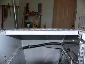 The rivets that hold the hinge for the forward baggage bay posed a particular challenge. I thought I could get them with my squeezer, but there wasn't room to get the yoke in there. I used to have a "no hole" yoke that would have worked, but the guy who bought my pneumatic squeezer wanted it, so I sold it to him.
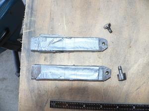
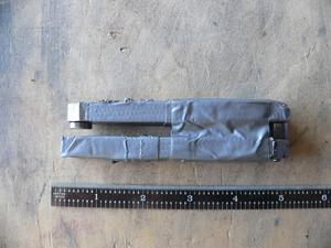 I pulled out the Rube Goldberg tool I had made to help rivet the nutplates on the edges of floor (a mod - not part of Van's design). There wasn't room to get a squeezer on those rivets, so I got some scrap steel bars, drilled holes to take rivet dies, and put the squeezer on the bars to squeeze the ends together. It worked quite well.
I reinserted several switches that I had removed to provide access to rivets, and riveted the channels on that bridge the forward and aft portions of the F-804 bulkhead.
I don't have those CherryMax rivets yet, but they can be done anytime. I've got two more rivets I need to do at the front corners of the skin. The engine mount limits access to squeeze those rivets, so I'll probably have to pull out the rivet gun for those.
Forward Skin - Finally Starting to Rivet
- Details
- Written by Kevin Horton
- Hits: 4982
It still amazes me how much longer things can take than you expect. Way back in late June I thought I was almost ready to start riveting the upper forward skin on. I could think of three things that I needed to do first, then I could do that skin. Then I did a detailed inspection of the forward fuselage area, looking for things that either had to be completed before I riveted that skin in place, or things that would be much easier to do before putting that skin on. I came up with a list of about a dozen things that I should do before riveting the skin.
I started working down that list, then I decided to add a Narco 122D as a second independent navigation aid. Then I discovered an annunciator light problem that I should fix before putting the skin on. And I kept my eyes open as I worked, and kept on finding more things that I needed to correct before I closed off access to that area.
On Friday, I thought I would be ready to start riveting that skin on Saturday morning. Then I spied two more problems that needed sorting out (brake lines and a wire bundle that were chafing on a bulkhead corner.
This morning I thought I was finally ready to go, and I clecoed the skin in place. I was all ready to start riveting when I realized that it would be difficult to get the canopy bow in place once the skin was attached. I grabbed the canopy bow to see if it could be manoeuvred in place - not a chance. So, the skin had to come off, I had to prime the little pieces that attach the skin to the aft face of the canopy bow, bolt the canopy bow in place, torque all the bolts, rivet those little pieces onto the aft edge of the skin, then cleco it all back again.
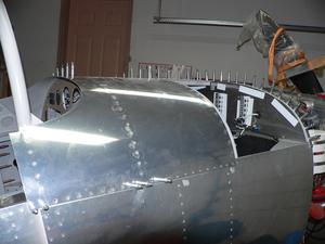 This evening I finally started riveting the skin in place. I've only got about 30% of the rivets in, but it is going well so far. I'll do all the ones I can reach, then entice Bruce, a local RV-3 builder to come help me get the rest.
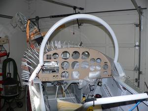 The instrument panel is screwed in place, as other builders have found that if you don't do that you will have problems getting it in later. Apparently the stress of riveting causes things to shift a bit, and the instrument panel will no longer line with the holes that it screws to. But, if you have it screwed in place when you rivet, it holds things in place.
The four "round dial" engine instruments are laying wrapped up in some foam to protect them from the vibration from the rivet gun. There are a lot of wires attached to those instruments with ring terminals (three to five per instrument), so it is easier to leave then attached to the wires once I finally got them hooked up properly.
MSTR WARN Lamp Dimming Finished, Finally
- Details
- Written by Kevin Horton
- Hits: 4477
I am very, very pleased to report that the MSTR WARN dimming is finally working.
I purchased Zener diodes with two different values on Friday, and tried them both in my jumper-wired proof of concept. I selected the one that gave the best balance with the other annunciators lights, and did the wiring mod to put it in the circuit. It works perfectly.
I have invested much more time and thought in the annunciator lights than I had expected, and I have drawn two lessons from this saga. The first aborted effort was triggered when I was told that 12V bulbs for the Vivisun annunciators I used were rare and very expensive. I was told that I would need to acquire a 24V to 24V DC-DC converter, and a particular one was recommended. I took this advice at face value, and ordered the recommended converter, only to discover that the recommended mod to the converter involved replacing microscopic surface-mount components, which was well beyond my capability. I then e-mailed Vivisun to inquire about 12V bulbs, and found that they were readily available. Vivisun's price was a $5/bulb, but other vendors had them for much cheaper.
Lesson #1 - Don't make big decisions based on information from a single source, if possible.
My second mistake revolved around the way the MSTR WARN annunciator worked. I had noted that the sample wiring diagram provided for the Engine Monitor had the MSTR WARN lamp wired in a strange way. I studied that drawing, could not understand it, and decided to ignore it. Later on, after first wiring up the MSTR WARN lamp, I noted that it was always ON, rather than flashing as the instructions suggested it should be. I assumed that the instructions were perhaps out of date. Of course I eventually learned that the wiring diagram provided for the Engine Monitor was correct, and that the lamp would flash if it was wired correctly.
Lesson #2 - Pay attention to discrepancies. If something doesn't match up there is probably a good reason, and the sooner you find it the less grief it will cause you.
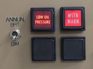
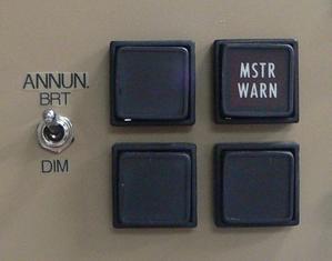 Here is what the annunciators look like without power.
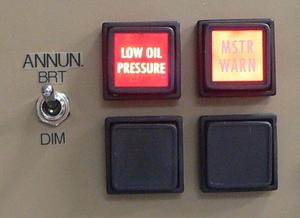 Here they are with the MSTR WARN and the LOW OIL PRESSURE annunciators illuminated in BRT mode.
MSTR WARN Lamp Dimming Progress
- Details
- Written by Kevin Horton
- Hits: 4763
I had a hard time getting to sleep Tuesday night, as my brain wouldn't stop thinking about the MSTR WARN annunciator dimming. I finally came up with another possible idea, and was able to go to sleep. I tried my concept out last night, using a bunch of jumpers with alligator clips to hook up a test - I couldn't get it to work. I finally gave up in frustration.
I pondered the problem a bit more today, and eventually realized that I hadn't properly hooked up the jumpers to test my concept on Wednesday. I had another go at it tonight, and managed to get the MSTR WARN dimming working. The only catch is that it is a bit too dim in dim mode, so I need to purchase a different value Zener diode to sort that out.
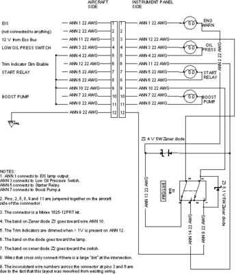 I was able to get the dimming working by tapping into the trim indicator dim signal, which is run from the second poles on the BRT/DIM switch. Hopefully I'll be able to find a suitable Zener tomorrow, so I can get this working this weekend.
MSTR WARN Lamp Dimming Frustration
- Details
- Written by Kevin Horton
- Hits: 5734
Today I made quite a bit of progress at cleaning up the wiring in the forward fuselage. Then I decided to troubleshoot the MSTR WARN annunciator lamp that is triggered by the EIS 4000 Engine Monitor. This lamp wasn't working correctly, and I didn't understand why. I eventually spied a wiring problem, and "fixed" it, but the light still wasn't illuminating. I studied the Installation Manual more closely, and was horrified to note that I had completely misunderstood how it was supposed to be controlled. I had wired it so that it needed to get power from the Engine Monitor to illuminate. But, the Engine Monitor is designed to provide a ground when the lamp is supposed to be active. :(
This would be an easy fix, if I didn't want to be able to dim this lamp at night. I spend quite a while looking at various possible solutions, and came up with three options.
- Completely rewire the dimmer control, replacing the existing two-pole switch (and one Zener diode) with a three-pole switch, and two Zener diodes. Two of the poles would mirror the existing installation (one pole to control the lamps that need power to light, by putting the Zener in the common ground, and one pole to control trim indicator dimming). The third pole would control the MSTR WARN lamp by putting the Zener in its switched ground. This would be a big mod, and I didn't look forward to trying to solder two Zener diodes to a three-pole mini switch.
- Add a relay with a Zener diode, and control the relay by the trim indicator dim signal. The trim indicator dimming is controlled by the second pole of the dimming switch - the LED trim indicators go into dim mode when power is applied to the dim enable wire. I could tap into this wire to control a relay, and the relay would put a Zener diode in the switched ground that controls the MSTR WARN lamp. This would be fairly easy to add to the existing wiring, but it means I need to make yet another trip to the electronics store, and I need to find a place to mount the relay, it adds extra weight and complication. Plus it adds new failure modes that could keep the MSTR WARN lamp from lighting.
- Rewire the MSTR WARN lamp control to bypass the dimming control. This would be a simple fix, but the MSTR WARN lamp would always be in bright mode. I didn't like this idea at first, but warmed to it after some thought. I don't plan to fly at night too often. Normally, the MSTR WARN lamp should only illuminate before engine start (due to low oil pressure, and low bus voltage), and after engine shutdown. It should never illuminate in flight, unless one of the monitored parametres exceeds the preset limits. If the parametre goes back inside the allowable limits, the lamp will extinguish. If not, and the bright lamp is distracting, I can extinguish it by either pulling it slightly towards me, which will disconnect it from its socket, or I can change the limit on the parametre that is triggering the lamp. There is one bonus to this mod - it removes the risk of inadvertently flying with the BRT/DIM switch in DIM mode, and not seeing a lit MSTR WARN lamp because the sun is so bright.
I'll sleep on it tonight, but I will almost certainly rewire the MSTR WARN lamp so it is always bright.
Narco 122D Progress
- Details
- Written by Kevin Horton
- Hits: 4677
The Narco 122D installation is coming along nicely. I hadn't planned on having this item when I did the wiring, so some of the wiring was in the way of where the far end of the 122D needed to go. It took a bit of doing, but I managed to move several wire bundles and secure them so they wouldn't rub on the Narco box.
I got the electrical installation for the Narco finished yesterday. It took quite a bit of study of the Narco 122D Installation Manual to figure out how to wire the connector - my first attempt didn't work, but I figured out how I had misinterpreted the manual, and the second try was a winner. I had to modify the DB-37 connector, as it originally hit a lateral stiffener at the aft end of the forward luggage compartment. I managed to cut part of the connector backshell away, and then patch the hole in it with 5 minute epoxy.
Today I figured out where to mount the Comant CI-1125 dual VOR/glideslope diplexer, which takes the signal from the Nav antenna, pulls the glideslope signal out, and splits the nav and glideslope so they can each go to two receivers. Tonight I tried to make up the coax cables, but found that the RG-400 coax ends I had were not compatible with the RG-58 coax - I thought those two coax types used the same connectors, but not so.
