Bill Randolph Arrives Home After Around the World Flight
- Details
- Written by Kevin Horton
- Hits: 3221
Bill Randolph arrived back home after his flight around the world in his RV-8. It took him 2 1/2 months, with a long list of adventures along the way, but he did it. Way to go!
Back Home, Finally
- Details
- Written by Kevin Horton
- Hits: 3188

Saturday I was very tired from the overnight trip back from Brazil. Sunday I had to do some dryer vent repair work, and spend time with Terry. This afternoon I attacked the oil cooler door linkage. The work started off poorly when I countersunk some holes on the wrong side of the sliding door, which meant I needed to throw the old one on the scrap heap and make a new one, which wasted two hours. But, the new one turned out OK, so I moved on to making a prototype linkage from wood, to test out the geometry. I didn't quite get it finished, but it looks like it should work.
Harvard Flight
- Details
- Written by Kevin Horton
- Hits: 5618

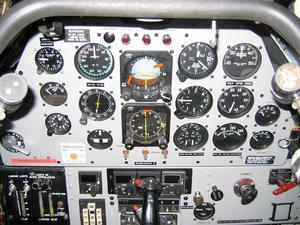
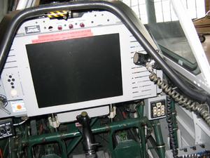
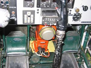
NRC is currently running a flight evaluation of a novel non-linear airspeed and altitude tape format for EFIS or HUD displays. The rear cockpit has a large flat panel display that covers most of the instrument panel. The display is powered by a PC computer system, and it currently displays a large EFIS type display, with vertical airspeed and altitude tapes. I am one a large number of evaluation pilots who will be stuck "under the hood" and have to fly various manoeuvres using linear and non-linear display formats, so the performance can be compared.
The weather didn't cooperate today, so although we got airborne, we never found a suitable test area - too much low cloud. It was a hoot to fly the Harvard though (I only flew it up and away - Rob Erdos had to do the take-off and landing, for obvious reasons). The Harvard is fairly large, and built like a tank. It has a huge amount of adverse yaw, and needs a lot of rudder anytime you move the ailerons. I'll get another shot at this sometime in June - hopefully the weather will workout next time, or I might have to do this again :). It was good to fly with Rob again - we hadn't flown together since we were both at the Aerospace Engineering Test Establishment, way too many years ago.
Weight Limits in Canada - Part 2
- Details
- Written by Kevin Horton
- Hits: 4558
Back in JanuaryI mentioned a uniquely Canadian regulatory issue revolving around wing loading and weight limits. I fired an e-mail off to the TC guy in charge of this stuff, and finally heard back from him last week.
The amateur build regs in Canada specify a maximum wing loading (see AWM 549.103)- if the aircraft's wing loading is too high, then it is classified as a high performance amateur-built aircraft, and that triggers a requirement that any pilot hold an individual type rating for that aircraft. The hoops you need to jump through to get an individual type rating are aimed at type-certificated aircraft, as they require ground training, etc. They need to be liberally interpreted to allow the square-peg amateur built aircraft to fit in the round regulatory hole.
CAR Standard 421.40 lays out knowledge, experience and skill requirements that must be met to obtain an Individual Type Rating for a High Performance Aeroplane. The experience requirement is easy to meet, as it is only 200 hours total time on all aircraft types. The knowledge requirement is a bit more difficult, as it calls for ground training on the aircraft type. But, this is only a standard, not a regulation, so there is a bit of room for interpretation. My friendly TC guy recognizes that a formal RV-8 ground school does not exist, so I simply need to convince him that I know everything I need to know about the aircraft. Given that I built it, that won't be too difficult. The skill requirement is met by my friendly TC guy climbing in the back and giving me a check ride. I suspect many TC inspectors would not feel comfortable climbing in an amateur-built aircraft, but I am lucky that this guy has an open mind.
My plan is to initially declare a gross weight of 1800 lb. After the flight test phase is complete, and I can carry passengers, I will do a check ride, obtain the individual type rating for an RV-8 then file the paperwork to increase the gross weight.
I suspect that many Canadian amateur-built aircraft owners are either ignorant of the wing loading regulation, or are ignoring it. Aircraft like Harmon Rockets, some Lancairs, etc probably have declared gross weights that require the pilot have an individual type rating, but I bet many of the pilots don't have one. They may think they have slipped on past TC, but their insurer could have the last laugh, as this would give them an easy reason to deny payment if there was ever an accident.
Upper forward skin, oil cooler door control, etc
- Details
- Written by Kevin Horton
- Hits: 4038
I did a bit of wiring cleanup this weekend, did some prep work on the upper forward fuselage skin and spent a lot of time pondering the control linkage for the oil cooler door.
I'm slowly getting to the stage where I will be able to rivet the upper forward fuselage skin. I countersunk most of the holes where the lower edge of that skin overlays the upper longeron. There are eight rivets on each side that have very, very poor access due to the top of the landing gear boxes. A few brave builders manufacture special bucking bars to get at those rivets, but I've got so much stuff going through the landing gear boxes that I will do what most builders do - use blind rivets. The rivet of choice seems to be the CherryMax CR3212-4-4. Some builders (e.g. Larry Bowen) have used the CR3214-4-4, which has a smaller head, but I'm not happy with putting eight of those in a row, as the small head and big diameter of those rivets wouldn't produce as much "pull" strength as the solid rivets that the plans call for.
I drilled the holes for the CherryMax blind rivets out to 1/8 inch (the solid rivets used everywhere else on this skin are 3/32 inch diameter). I countersunk the 3/32 holes, and deburred and dimpled some of the holes on the skin (I only did the ones that needed the C-Frame dimpler and hammer, as that makes too much noise to do early in the morning, when Terry is still asleep).
One of the last big tasks I need to do before riveting this skin is to fabricate and install the control for my oil cooler air door. I built the sliding door a long time ago, but I never sorted out the control linkage. I had a couple of big-picture concepts, but they fell apart once I started pondering the intricate details. I spent quite a while sketching various concepts, cutting up cardboard to try mockups, and think I finally have a workable concept. One of the hardest parts was figuring out exactly which Bowden cable to order - there are so many different types, each with its own peculiarities. I don't have a lot of room to work with, so I needed to consider exactly how each type of Bowden cable would be secured, and how it would attach to the linkage before I could come to a decision. Anyway, I ordered a cable and all the attachment hardware. We'll see in a few weeks whether this plan will do the job.
I also painted the brackets for the heater box control, so I can install them later this week.
Annunciator Lights Control - Round 3
- Details
- Written by Kevin Horton
- Hits: 3858
We were out of town last weekend, and I was out of town for a few days last week. I've spent way too much time trying to sort out the annunciator control and dimming. I was told that 12v bulbs for these annunciators were "unobtainium", and that I needed to use either 5v or 28v, as these were the two voltages available. This meant I needed some sort of DC-DC voltage converter, and a circuit to control the annunciators. The circuit to control the annunciators wasn't too hard to sort out, but the DC-DC converter evaluation board proved more troublesome. I obtained a National Semiconductor DC-DC converter evaluation board, which was advertised as being easily modifiable to work at various input and output voltages. But, this board used tiny surface-mount components, that are way beyond my ability to modify. I would need to hire the modification job out to a professional shop, which would run the costs up even further.
Last weekend I spent some time with my brother, who is a senior guy at a large aircraft mod shop. He said that they often had to change the operating voltage of annunciator bulbs when they did avionics upgrades. He said that they might have some 12v bulbs laying around, as most modern avionics used 5v annunciators.
Learning that 12v bulbs for my annunciators might actually exist caused me to do something I should have done months ago - I contacted the manufacturer. They told me that 12v bulbs were available, at a cost of $5 each. I need four bulbs per annunciator, plus some spares, so figure on $100 total. That isn't a lot in the big picture, as it means I wouldn't need a separate control circuit, nor a DC-DC converter. I would end up with a simpler, lighter, more reliable installation. So, I'm going to order some 12v bulbs, and drop the control circuit and the DC-DC converter. Each bulb will get its power from the box or circuit that drives it. The dimming will be done by switching a zener diode into the common ground for the bulbs. The voltage drop across the zener diode is essentially constant, no matter how much current is going through it. So it can be in a ground line that is common for all four annunciators.
I spent several hours working on the heater box controls. My original concept for routing the Bowden cables proved unworkable, Plan B wasn't any better, but Plan C looked promising. I made up some brackets for Plan C and drilled the holes where they will mount to the firewall. Now I need some warm weather so I can prime them in the driveway. I attached the heater boxes to the firewall, and hopefully I won't have to take them off again.
