Mike Shields Coming Back Across the Atlantic Today
- Details
- Written by Kevin Horton
- Hits: 3411
Mike Shields is planning to leave Scotland today to start his way back to Canada in his RV-7A. It isn't clear from the available info exactly how many stops he plans to make, but he is planning a stop at Narsarsuaq, Greenland (BGBW). More info may be available later at:
Getting the Narco 122D in its hole.
- Details
- Written by Kevin Horton
- Hits: 4869
I made the cutout in the panel, following the guidelines in the Installation Manual, except I considered that the cutouts around the knobs in the corners were a bit bigger than necessary. So, I tried to make those cutouts a bit smaller, to have a more visually appealing fit. Then I tried to fit the instrument in the panel. I couldn't figure out how to manoeuvre it into place. It was like a Chinese Puzzle. I had removed the Power/Volume knob at the to right corner, as that shaft fit though a corner. But I expected that the other knobs would just slip into the cutouts. Nothing doing. I removed the Course Select knob at the lower left corner, but I couldn't figure out how to remove the Frequency knobs at the lower right corner
I tried to get it in the hole for 30 minutes - no luck. I finally cracked, and posted a request for help to the RV-List and the Aeroelectric-List. Then I decided to try one more time. Of course I figured it out right away, now that I had asked for help.
How do you get the Narco 122D in its hole?
- Make the cutout at the top right and bottom right the full size called out in the Installation Manual - don't try for too tight a fit.
- Remove the Power/Volume and Course Select knobs (you need a Torx T-5 tool).
- Remove the sleeves over the Power/Volume and Course Select shafts.
- Slip the Power/Volume shaft into its hole.
- Push the unit up against the panel, so the right side of the unit is touching panel.
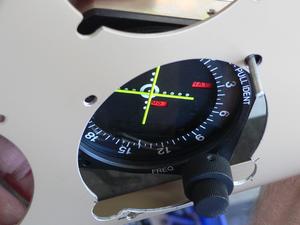
- Twist the unit so the Frequency knobs slip into their cutout. Enlarge the bottom of this cutout if necessary.
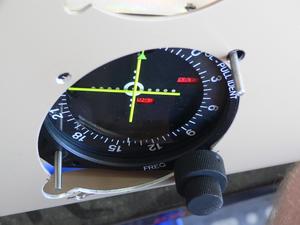
- Slip the Course Select shaft into its cutout.
- Install the two screws, the bushing on the Power/Volume shaft, and the knobs you had removed earlier.
- Note: I didn't have screws that were short enough, hence I had to put washers under the screw heads. I need to purchase #6 screws 1/2" long.
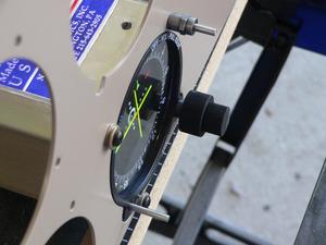
Lesson learned - use the cutout dimensions in the Installation Manual, even if they are "obviously" too big. If you want to make a smaller cutout, try it on some scrap first to see whether it will work.
Narco 122D Mechanical Installation
- Details
- Written by Kevin Horton
- Hits: 4275
This week I finished the wiring for the annunciator dimming. I wired them up early in the week, then did a functional test. I noted that something strange was going on - the Boost Pump annunciator lit up whenever the Brt/Dim switch was in Dim mode, and one of the other annunciators was lit, even though the boost pump as Off. It took a lot of head scratching, but I eventually figured out that I had current flowing in reverse through the Boost Pump motor windings. If the Brt/Dim switch was in Dim, the point where all the annunciator grounds were connected as at 5.1 V, if there was a lamp illuminated. But, the other end of the Boost Pump lamp circuit went through Boost Pump motor to ground. So, the lamp was getting a current through it, and it lit up. I noted that the same thing could happen to the Starter Relay lamp, but it wasn't seen now because I hadn't connected the starter motor to the starter contactor (I didn't want to risk having the motor turn over). I eventually figured out that I needed to put diodes in the circuits for those two lamps to prevent reverse current flow. Then I had to figure out how to mechanically add the diodes, so that the installation would be robust. It was an easy mod, once I discovered what the problem was, and figured out how best to install the diodes. But it cost me most of a day.
The Narco 122D finally arrived on Wednesday afternoon. Thursday I spent the whole morning trying to figure out exactly where to make the 3 1/8" hole for the 122D - I needed to put it high enough so it wouldn't hit the cross bar that goes between the landing gear boxes, and I needed to put it as low as possible so the instrument spacing looked consistent. I installed the instrument panel, and clecoed on the forward fuselage upper skin, as it held the instrument panel at the right angle. I took a gazillion measurements, then finally sorted out exactly where to make the hole.
I pulled out the fly-cutter, and saw that the cutter had a pretty had burr on it. It might work OK, or it might catch and destroy the instrument panel. I had too much time and money invested in it to risk destroying the panel, so I headed to Home Depot to buy a new fly-cutter. I decided to look for a 2-56 screw I needed while I was out (I had lost one of the screws for the Ray Allen trim indicators). I had t go to four different places before I finally found what I needed, but I learned that Valley Hardware has a very impressive collection of small bolts and screws (I needed 2-56 x 3/8 inch, flat head, black, but they had much smaller ones than that).
The new fly-cutter did a great job on the hole, then I hacked out the cut outs for the knobs at the corners. I discovered that I had to remove the knobs to get the 122D in the panel, and I didn't have the required tool - you need a Torx T-5 to remove the set screws. So, back in the car, for another epic journey around the city until I finally found the tool I needed.
Then I had to get the 122D in the the panel. Someone else wanted to get pictures to explain how that worked, so it is the subject of a separate article.
Today, finished cleaning up the various holes and cutouts so the 122D would fit in the panel. The Installation Manual called out a requirement for a support at the other end of the 122D. That made sense, as it was only held by two screws at the instrument panel end, it is quite heavy, and my aircraft will be able to pull 6g, or push to -3g.
But, it wasn't obvious how to make the support for the other end. You couldn't really see the other end, and it was quite close to the 803 bulkhead. I ended up crawling in the cockpit head first so my head was under the instrument panel to see the area in question. I must have crawled in there a a dozen time before I had figured out how to make the rear support, and where to drill the holes. It was a real pain, on my head, working by feel, but it all turned out great in the end, after several hours of work.
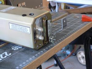 Here you see the bracket I bent up to support the other end of the 122D. This bracket is now bolted in place in the forward fuselage.
I had to push some of the wiring out of the way to get the 122D in place, so now I need to figure out how to secure that wiring so it won't chafe. And I need to connect the various wires and antennae to finish the installation.
Narco 122D
- Details
- Written by Kevin Horton
- Hits: 9952
I reviewed the Canadian IFR equipment requirements again, and have concluded that I really need to add a completely independent second IFR approach capability. Canadian Aviation Regulations (CAR) 605.18(j) says:
Power-driven Aircraft - IFR605.18 No person shall conduct a take-off in a power-driven aircraft for the purpose of IFR flight unless it is equipped with... (j) sufficient radio navigation equipment to permit the pilot, in the event of the failure at any stage of the flight of any item of that equipment, including any associated flight instrument display, (i) to proceed to the destination aerodrome or proceed to another aerodrome that is suitable for landing, and (ii) where the aircraft is operated in IMC, to complete an instrument approach and, if necessary, conduct a missed approach procedure.
My original plan was perhaps affected by my experience in type certification of aircraft designs. The regulations that govern type certifications have a concept of Equivalent Safety (see CAR 511.07(1)(b)). A manufacturer may argue that although his design does not meet the literal wording of the requirements, it has special features, or will have Flight Manual Limitations, that make the design equivalently safe to one that met the requirements. This allows us to sometimes focus on the intent of the requirement, rather than the literal wording.
I viewed the intent of CAR 605.18(j) as being to ensure that the aircraft can safely get on the ground after any single failure of any item of the navigation equipment, including displays. I have a Garmin GNS430, which has independent NAV and GPS, but they are both managed by the GNS430's display. If that display fails, it is not possible to change the NAV frequency, or manage the GPS. So, I planned to put a Limitation in my POH, requiring that either the destination or alternate airports have weather that allowed a VFR descent and landing. If the GNS430 failed on an IFR flight, I would pull out my handheld GPS and use it for enroute navigation, and then count on the VFR weather at either my destination or alternate.
But, these equipment requirements are not aircraft certification requirements, they are what we refer to as Operational requirements. And the concept of Equivalent Safety does not exist in operational requirements. You either have to meet the literal wording of the requirement, or you need an official Exemption from the requirements. Exemptions are difficult to obtain, and they are only valid for one or two years - they are intended as a solution to a temporary problem, they are not supposed to be a permanent "let" to the requirements.
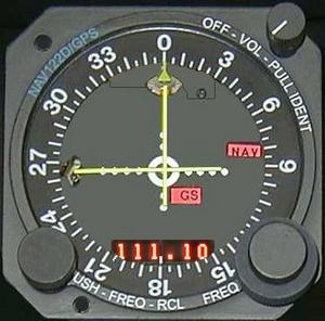 So, I really need to add a second independent IFR navigation and approach aid, if I want to eventually obtain an IFR approval. I had originally considered a Narco 122D, which is a VOR/ILS receiver contained in the same box as its indicator. It fits in a standard sized instrument hole - you provide power and hook up the antennae, and you have a self-contained second IFR navigation capability. I decided to purchase a Narco 122D, and all the other miscellaneous items that I will need to install it. It will fit right below the CDI. It will be easier to install it now than later, so I will order it on Monday, and move on to other things while I wait for it to arrive. I'll probably start the engine baffle plenum cover.
Forward Fuselage Progress
- Details
- Written by Kevin Horton
- Hits: 2971
I'm slowly working through the list of things I need to do in the forward fuselage. This week I finished the wiring for the Electronic Ignition, and started the dimmer wiring for the Vivisun annunciators. I managed to get the zener diode soldered to a tiny little toggle switch yesterday, and confirmed that my concept works by connecting everything up with jumper cables. I just need to hook everything into the existing wiring. I also finished off several little items.
Mike Shields Flies RV-7A Across the Atlantic
- Details
- Written by Kevin Horton
- Hits: 3634
Ontario RV-7A builder Mike Shields has flown his aircraft across the Atlantic. He flew from Ontario to Halifax, NS on July 3rd, to Iceland with a stop in Goose Bay, Labrador on the 4th, and to Scotland on the 5th. You can get info at:
He has Jon Johanson's tip tanks, plus a 32 USG flexible fuel cell on the pax seat, for 93 USG total fuel.