Fuel Tank Frustration
- Details
- Written by Kevin Horton
- Hits: 4900
Not a productive week :(. I did two rounds of prime, fill and sand on the windscreen fairing. Yesterday I had to do a bunch of "get ready for winter" stuff, so no progress. Today, I planned to Proseal the access covers onto the fuel tank so I could do the leak tests. But first, I thought I should take the tanks up to the garage to hook the fuel level senders to the wires to the fuel gauges to make sure everything worked OK. Another local builder had reported that he had to tweak the bends in the wires that hold the floats on the fuel senders to get the gauges to read zero when the float hit the bottom of the tank.
I figured it would only take a little while this morning to test the fuel senders, then I could mix up the Proseal this afternoon. Piece of cake, right? Wrong! I had overlooked the fact that the tanks were currently attached to the wings. I had put them on the wings to check the fit, and had never taken them off. And the wings were in a stand, leading edge down. I pulled the screws off that held the aft end of the left tank skin to the spar - a real PITA for the surface that faced the other wing, as I had to squeeze into the space between the wings on the wing stand. I removed the bolts that hold the aft face of the tank to the spar, put the end of the main spar on a support to take the weight off the leading edge, and tried to remove the left tank. Nothing. No movement. I looked for screws or bolts that I had forgotten to remove, found one, removed it, and tried again. Still no movement. I pulled harder. Nothing. More looking, more pulling. Still nothing.
I eventually gave up in frustration, as I couldn't get the tank to move, and I was afraid to pull too hard and bend something. I'll pull out the mirror and light tomorrow night to have a closer look for fasteners that I missed. And Terry got back tonight from a weekend away, so she can help me pull the wing out of the stand so I can get better grip on things.
Airspeed Indicator Calibration - Round 2
- Details
- Written by Kevin Horton
- Hits: 8022
I spent several hours yesterday doing an airspeed indicator calibration. I had done one before, back in April 2004, but I had some problems with the water manometer, which made me question the accuracy of my data. And I didn't do a very good job at recording EFIS airspeed data, so I didn't have a good handle on how accurate it was.
The EFIS had gone back to the vendor for a hardware upgrade a month ago, and the one I received had a different serial number from the one I sent. It was a major hardware upgrade, so they probably send out new units, and then rip the old ones apart for the components that can be reused. I was curious to see how the instrument error of the new EFIS compared to my original one.
This time I clamped some pieces of wood on either side of the clear tubing to keep it from moving around. Last time the tubing was just hanging, which allowed it to swing from side to side and set up some motion of the water inside. I also moved the tubing much more slowly when I was changing the water level, to be sure to stay on the same side of the hysteresis band. And I recorded more EFIS data, at a higher data rate (15 seconds at 8 records per second).
I finished crunching the data this morning. I was gratified to see that the general trend of the results were very similar to that I measured in April 2004. That means my previous data was probably better than I thought, my technique is repeatable, and the errors are relatively stable with time.
Note that there is a certain amount of error associated with each measurement, so the results are only approximate. The measurements of water manometer height are probably only good to 1/16 on an inch (this represents 1.2 kt at 40 kt, and 0.2 kt at 200 kt), and it is hard to read the analog ASI to better than half a knot. Thus the total error in this data is about 1.7 kt at 40 kt decreasing to 0.7 kt at 200 kt. The EFIS data resolution is 0.2 kt, so the total errors in the EFIS ASI error plots is about 1.4 kt at 40 kt, decreasing to 0.4 kt at 200 kt.
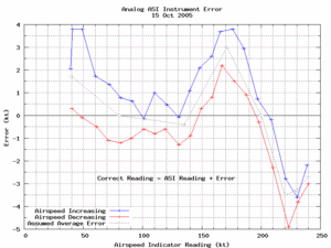 Here is the latest data for the analog ASI. The range of interest for normal operations is from about 50 kt (stall speed) to 200 kt (Never Exceed Speed). I will do some flight testing in excess of 200 kt, so I did the calibration out to about 240 kt.
The hysteresis in the analog ASI is not surprising, as it is a mechanical instrument with some internal friction.
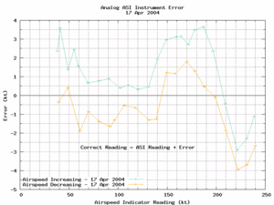 Here is the data from last year. You can see that it is quite similar to yesterday's data.
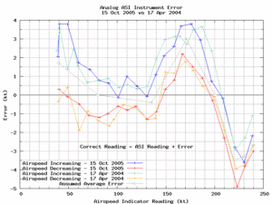 This plot shows both sets of data for the analog ASI. The two sets of data compare very well, taking into account the errors inherent in the measurements (about 1.7 kt at 40 kt decreasing to 0.7 kt at 200 kt).
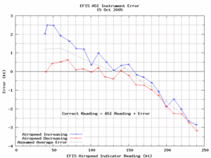 Here is the latest data for the EFIS ASI. I compared the EFIS ASI screen indications to that shown on the data stream, and they seemed to match up perfectly (as they should). I used the EFIS data values for these plots, as they had more resolution than I could have read from the screen.
The apparent hysteresis in the EFIS ASI has me puzzled. I don't know if this hysteresis is in the EFIS, or maybe it is in the water manometer. It is possible that I am slightly misreading the manometer due to the viscosity as the water moves in the tube between test points. This error would be in the correct sense to at least partially explain the apparent hysteresis.
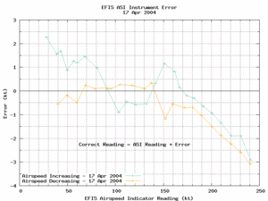 This plot shows the data from last year for the EFIS ASI. The results look quite "noisy" in the range of 90 to 150 kt. I was having problems with the plastic tubing for the manometer swinging around, which would start the water moving, which probably reduced the hysteresis, and reduced the accuracy of my measurement of the water height. I have a lot more confidence in yesterday's data.
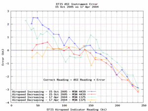 This plot shows both sets of data for the EFIS ASI. The general trend is surprisingly similar to the original EFIS. I'm scratching my head trying to figure out if there could possibly be some sort of systematic error in my test technique, but I think this is more likely a sign of manufacturing consistency in the sensors used in the EFIS.
Remote Compass Sensor Mount Redux
- Details
- Written by Kevin Horton
- Hits: 5990
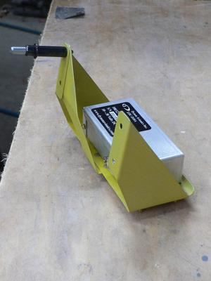
The updated EFIS hardware came with a new Remote Compass Sensor. For some strange reason the newer model Remote Compass Sensor has a different pin-out on the connector, so I had to disassemble the connector to move two sockets to different spots on the connector. This would be a fairly easy job on the bench, but I had to do it way in the back of the fuselage, after crawling in head first. The connector was up at the top, but there wasn't enough room to lay on my back, so I had to lay on my side, and open it up, being careful to catch all 8 tiny screws, nuts and clips. Pulling and repositioning the pins wasn't too hard, and I managed to get it reassembled without losing any of the hardware.
 I primed the Remote Compass Sensor bracket, bolted the sensor to it with non-magnetic brass hardware, then crawled back into the fuselage again to bolt it in place. It felt great to get that done.
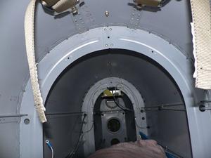 Here you can see how far back in the fuselage the Remote Compass Sensor is mounted. It is two thirds of the way back from the bulkhead behind the rear seat to the leading edge of the horizontal stabilizer.
Last night I had a nagging worry, as I recalled that the sensor needed to be well aligned with the EFIS. I had this distant thought that I had discovered in the past that I needed a shim, and I had forgot to put it in. Today I reviewed my notes from when I fabricated the mount, and sure enough, I found I needed a shim to get the alignment correct. I reviewed the EFIS Installation Manual, and it said that the Remote Compass Sensor should be aligned within 0.2 degrees of the EFIS.
Tonight I installed my old instrument panel blank, and measured its vertical alignment with a digital level. I crawled back in the fuselage, and measured the alignment of the Remote Compass Sensor. Sure enough, it was tipped forward almost 4 degrees from what the EFIS was. Drat.
I removed the mounting bracket, which allowed me to discover that the low strength LockTite that I had used on the brass hardware didn't provide nearly as much locking power as I had expected. It is a good thing I discovered this, as I believe that the bolts would have eventually have vibrated loose.
I found a combination of washers and brass nuts that tipped the sensor the required amount. As near as I can measure, it should end up within 0.1 degrees of the EFIS. The trick now is to never measure it again. :)
Now I just need to buy some medium strength LockTite and then I can bolt the mount back in place. And I noted a chafing problem between one of the static system lines and the mount which I need to address. I will be overjoyed to finally be done with the Remote Compass Mount.
Dynon D10A EFIS Data Recording Script Read Me
- Details
- Written by Kevin Horton
- Hits: 4152
INTRODUCTION
Perl script to record serial data from a Dynon D-10A EFIS. High resolution computer time is appended to each data record to facilitate time sync with other data.
This script works with Dynon software version 2.11 on the D-10A. Earlier software versions had a shorter data stream that is not compatible with this version of the script.
Three Perl modules are required:
- Time::HiRes (may be part of the standard perl distribution)
- Cwd (may be part of the standard perl distribution). If the Cwd module is not available, the script location can be manually specified in the code. See the comments in the code for more info.
- Device::SerialPort (OS X or Unix/Linux) or Win32::SerialPort (Windows). Win32::SerialPort is not part of the standard Activestate distribution of perl for Win32.
An OS X packaage for Device::SerialPort is available via the Fink package distribution system (http://fink.sourceforge.net/).
This script was tested on Apple OS X 10.4.2 with perl 5.8.6, but it should work on any Unix type OS. An early version was tested with Active State Perl on Windows 98, but it is not known if this version will work. A config file for Win32::SerialPort is included inside the "win" directory.
The data parametres to be recorded, their labels and scaling, are specified in the EFIS_data.config file. The default location of this file is the same directory as this script. This can be changed by specifying a new location with the variable "$EFIS_data.config".
WIRING
The EFIS must be connected to the computer serial port as follows:
     EFIS               Computer
   Connector           Serial Port
  DB-25 Female         DB-9 Female
    Pin 9  Pin 5
    Pin 10  Pin 2
    Pin 22  Pin 3
MUST DO
The following items must be completed by the user, or the script will not function.
- The serial port must be specified on lines 2 and 22 of the "EFIS.config" file. The rest of this file should be left as-is.
- The EFIS.config file must be located in the same location as the script, or the variable "$config_file" must be set to the config file location.
- Ensure the script permissions are set to be exectuable. In the terminal, run the following command "chmod a+x EFIS_data_capture.pl".
- Ensure both data files can be read. In the terminal, run the following command "chmod a+r EFIS_data.config EFIS.config".
SHOULD DO
The following items should be completed, but the script will use default values if they are not completed.
- Copy the "EFIS_data.config" file to the same location as the script, or set the variable "$EFIS_data_config" to the location of the file.
- Edit the "EFIS_data.config" file to set the desired default data rate, the list of variables to record, the order to record them, the labels and units to put in the file header, and the scaling factors to use. The default recording duration can also be specified.
If the "EFIS_data.config" file is not found, the script will use a default data rate of one record per second, record every variable, in a default order, with headers the same name as the variables, and no scaling. The data units will be as described in the EFIS User's Guide. - Change the default Data Element Separator and Record End Separator, if necessary to match what your spreadsheet or graphing program expects. The default is to use a Tab to separate data fields, and a line Feed between records.
- Specify an alternate data file location, if desired. The default data file location is the same location as the script.
HOW TO RUN THE SCRIPT
- Connect the EFIS to the computer, using a USB to Serial adapter if required.
- Turn on the EFIS.
- In the terminal, run "EFIS_data_capture.pl" to record at the default data rate. If something other than the default data rate is desired, run "EFIS_data_capture.pl n" where "n" is the desired data rate in records per second. E.g., for 2 records per second, run "EFIS_data_capture.pl 2". For one record every 5 seconds (i.e. 0.2 records per second), run "EFIS_data_capture.pl 0.2".
- To stop data capture, type "Ctrl-C". The data is only flushed to disk periodically - if you hit "Ctrl-C" before any data has been written, no data will be written at all.
- The data file will be saved in the same location as the script, unless the $DATA_FILE_LOCATION variable in the script is editted to specify a different location.
TO DO
The following changes may someday be added to the script.
- Add a loop to monitor the keyboard, and quit when ESC is pressed.
- Check code for detection of Windows, and add this functionality for config and data file locations.
- Add selectable record separator to data config file.
- Ensure $data_from_file is set to 0 prior to release.
- Rework command line switch to be -r X -d Y, where X is the data rate and Y is the duration in minutes.
- Done.
- Consider moving serial port parametres into the main script, and dropping the EFIS.config file. This may make the script more portable with Windows.
- Add code to specify the interval at which the data file should be written to disk.
DONE
The following TO DO items have been completed.
- Test what happens if the EFIS is turned OFF then ON during a data capture. OK. Tested on 9 Oct. Get an error on the Terminal screen, but the script keeps running, and it recovers OK once the EFIS is back ON. The script records garbage data while the EFIS is OFF, but it is quite obvious that the data is no good.
Author - Kevin Horton - This email address is being protected from spambots. You need JavaScript enabled to view it.
The author is not an experienced perl programmer. Experienced perl programmers would have written a much more efficient script. But the script works. Please send any suggested improvements to the author.
This script is free software. You can redistribute it and/or modify it under the same terms as Perl itself.
Rev 1 10 Oct 2005
Flight Test Data Recording Scripts Available
- Details
- Written by Kevin Horton
- Hits: 5794
I seem to have all the major bugs worked out of my EFIS and Engine Monitor data recording scripts, so it is time to expose them to the world. If I had an infinite amount of time, I would add several new features first, but there are only so many hours in the day.
These are Perl scripts that record serial data from a Grand Rapids EIS 4000 Engine Monitor and Dynon D10A EFIS. An earlier version worked with the data format of the D10 EFIS, so if anyone needs that, let me know and I will put a D10 version together.
There are two scripts available:
The scripts have been tested on OS X 10.4.2, but they should work with Linux, and may work with Windows, if you install Active State Perl. I had a very early version working with Windows 98, but haven't tested any recent versions.
These scripts are really ugly hacks, as I am not a professional programmer. Everything I know about Perl I learned from a book, a web site, or from looking at other people's work. I'm sure that experienced Perl programmers would feel ill if they looked at these scripts. But, despite that, they work, at least for me.
My Mac laptop doesn't have any serial ports, so I use a Keyspan USB 4 Port Serial Adapter (model USA-49LWC). If you use OS X, you might want the Fink package for the Perl Device::SerialPort module.
Note: Development has essentially stopped on these scripts, as someone with more skill than I has created a much nicer prototype script. I will attempt to fix major bugs if they are found, but I am unlikely to add new features.
Grand Rapids EIS 4000 Data Recording Script Read Me
- Details
- Written by Kevin Horton
- Hits: 4401
INTRODUCTION
Perl script to record data from a Grand Rapids EIS 4000. High resolution computer time is appended to each data record to facilitate time sync with other data.
Three Perl modules are required:
- Time::HiRes (may be part of the standard perl distribution)
- Cwd (may be part of the standard perl distribution). If the Cwd module is not available, the script location can be manually specified in the code. See the comments in the code for more info.
- Device::SerialPort (OS X or Unix/Linux) or Win32::SerialPort (Windows). Win32::SerialPort is not part of the standard Activestate distribution of perl for Win32.
An OS X packaage for Device::SerialPort is available via the Fink package distribution system (http://fink.sourceforge.net/).
This script was tested on Apple OS X 10.4.2 with perl 5.8.6, but it should work on any Unix type OS. An early version was tested with Active State Perl on Windows 98, but it is not known if this version will work. A config file for Win32::SerialPort is included inside the "win" directory.
The data parametres to be recorded, their labels and scaling, are specified in the EIS_data.config file. The default location of this file is the same directory as this script. This can be changed by specifying a new location with the variable "$EIS_data.config".
WIRING
The EIS 4000 must be connected to the computer serial port as follows:
                                 Computer
                                Serial Port
                                DB-9 Female
   Ground <----------------------> Pin 5
EIS 4000 Pin 9 <-----------------> Pin 2
 14 V Power <--------------------> Pin 6
MUST DO
The following items must be completed by the user, or the script will not function.
- The serial port must be specified on lines 2 and 22 of the "EIS.config" file. The rest of this file should be left as-is.
- The EIS.config file must be located in the same location as the script, or the variable "$config_file" must be set to the config file location.
- Ensure the script permissions are set to be exectuable. In the terminal, run the following command "chmod a+x EIS_data_capture.pl".
- Ensure both data files can be read. In the terminal, run the following command "chmod a+r EIS_data.config EIS.config".
SHOULD DO
The following items should be completed, but the script will use default values if they are not completed.
- Copy the "EIS_data.config" file to the same location as the script, or set the variable "$EIS_data_config" to the location of the file.
- Edit the "EIS_data.config" file to set the desired default data rate, the list of variables to record, the order to record them, the labels and units to put in the file header, and the scaling factors to use. The default recording duration can also be specified.
If the "EIS_data.config" file is not found, the script will use a default data rate of one record per second, record every variable, in a default order, with headers the same name as the variables, and no scaling. The data units will be as described in the EIS User's Guide. - Change the default Data Element Separator and Record End Separator, if necessary to match what your spreadsheet or graphing program expects. The default is to use a Tab to separate data fields, and a line Feed between records.
- Specify an alternate data file location, if desired. The default data file location is the same location as the script.
HOW TO RUN THE SCRIPT
- Connect the EIS 4000 to the computer, using a USB to Serial adapter if required.
- Turn on the EIS.
- In the terminal, run "EIS_data_capture.pl" to record at the default data rate. If something other than the default data rate is desired, run "EIS_data_capture.pl n" where "n" is the desired data rate in records per second. E.g., for 2 records per second, run "EIS_data_capture.pl 2". For one record every 5 seconds (i.e. 0.2 records per second), run "EIS_data_capture.pl 0.2".
- To stop data capture, type "Ctrl-C". The data is only flushed to disk periodically - if you hit "Ctrl-C" before any data has been written, no data will be written at all.
- The data file will be saved in the same location as the script, unless the $DATA_FILE_LOCATION variable in the script is editted to specify a different location.
TO DO
The following changes may someday be added to the script.
- Add a loop to monitor the keyboard, and quit when ESC is pressed.
- Check code for detection of Windows, and add this functionality for config and data file locations.
- Add selectable record separator to data config file.
- Ensure $data_from_file is set to 0 prior to release.
- Rework command line switch to be -r X -d Y, where X is the data rate and Y is the duration in minutes.
- Done.
- Consider moving serial port parametres into the main script, and dropping the EIS.config file. This may make the script more portable with Windows.
- Done.
- Done.
- Add code to specify the interval at which the data file should be written to disk.
DONE
The following TO DO items have been completed.
- Test what happens if the EIS is turned OFF then ON during a data capture. May need to greatly increase the timeout in EIS.config.
Tested on 2 Oct 2005 - There seems to be no problem with starting the script, then turning on the EIS, or with cycling the EIS power with the script running. It takes the EIS a few data records for the data to stabilize, but the script doesn't care.
- Add code to read the units from the data_config file and put them in the header. Tested on 8 Oct 2005.
- Add code to detect the path to the script, to avoid the need to specify the "$SCRIPT_HOME" variable.
Author - Kevin Horton - This email address is being protected from spambots. You need JavaScript enabled to view it.
The author is not an experienced perl programmer. Experienced perl programmers would have written a much more efficient script. But the script works. Please send any suggested improvements to the author.
This script is free software. You can redistribute it and/or modify it under the same terms as Perl itself.
Rev 1 10 Oct 2005
