Andair Fuel Valve
- Details
- Written by Kevin Horton
- Hits: 8530
Van supplies a brass fuel valve that looks like something you would find the the plumbing section of the hardware store. Most builders use it, and are happy with it, but I didn't like the industrial look or the way it felt when you turned it. Andy Phillips, a British RV builder has a business that supplies high quality components to the airline and expensive car industries. Andair sells a very nice fuel valve that I just had to have once I saw one. It has very nice detents at the Left and Right positions, and has a knob that you have to pull to get the valve into the Off position.
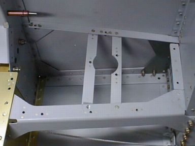 I mounted it in the same position that Van recommends putting the standard fuel valve, but I had to build up two custom brackets to hold it. The front bracket (right side of the picture) is riveted in place. The aft bracket mounts with #6 screws, as the fuel valve couldn't be put in place if both brackets were there first.
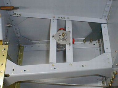 The fuel valve sits on top of the brackets.
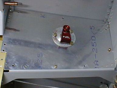 The cover sits on top of the fuel valve. I'm going to buy some round head screws to use instead of those three bolts.
Engine mount fitted
- Details
- Written by Kevin Horton
- Hits: 3675
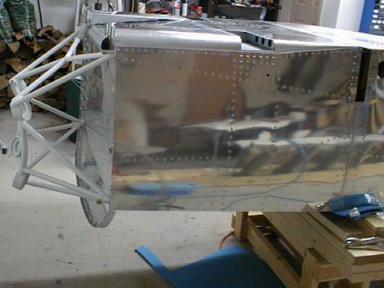 I was on the road this week from Monday to midnight Saturday night, so I got practically nothing done. Today, I drilled out a few rivets that I messed up last weekend on the belly fairing area, and redid them. Then I drilled the holes for the engine mount, and temporarily fitted it. I hope to get some friends over tomorrow to help me right the fuselage again, and the engine mount will make a nice handle on the front end of the fuselage.
Belly skin riveted
- Details
- Written by Kevin Horton
- Hits: 3830
I ended up going on the road this week for a couple of days, so I didn't get as much done as I had originally hoped. I did manage to get the belly skin area almost all riveted.
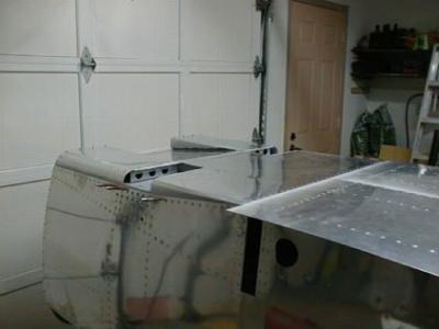 There is an opening on each side of the belly skin area where the landing gear legs attach. Those openings will be covered by removable covers.
You can also see the ramp where the cooling air and engine exhaust exit the cowling. The ramp forms a tunnel that allows this air to exit without adding a lot drag.
You need to be very careful when riveting the belly fairing area. Everything must be done in a very specific order, or you will find that you can't get access to buck some rivets. The sequence in the building manual works, but you have to read and understand every word. I almost painted myself in a corner a couple of times.
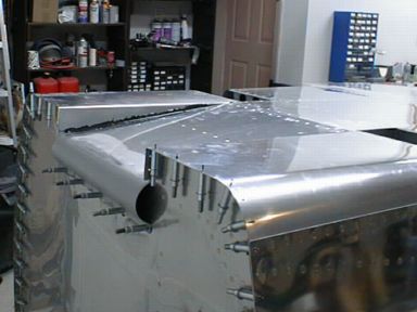 Here is a closeup of the cooling air exit ramp. The rounded edge on the front helps smooth out the airflow. There will be a lot of air exiting through a fairly small area, and Van has tried to make the airflow as orderly as possible to minimize the drag from the cooling air.
Inspection ports for forward fuselage subfloor
- Details
- Written by Kevin Horton
- Hits: 4114
In Canada, we have to get a series of official inspections done as we build the aircraft. One of the requirements is that any enclosed areas be inspected before that area is closed up. I suddenly realized that there were several enclosed areas in the forward belly fairing - I hadn't planned on having the next inspection done until much later in the project, so this posed a problem. I called the local inspector, and discussed the situation with him. He said that I really should have a way to inspect those areas for corrosion later in the life of the aircraft. If I had proper inspection provisions, he could use those to inspect those areas when he did my final assembly inspection.
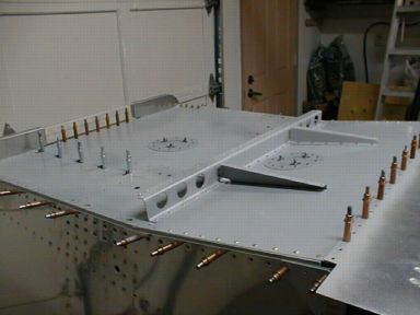 I wasn't too happy to hear that he wanted inspection ports, as that meant extra work, and a schedule slippage. But after calming down, I decided that he probably had a valid point, so I bit the bullet and studied the situation. There are optional lightening holes in some of the structure that could allow inspection, if I bought a slightly smaller inspection mirror. I could put a small lightening hole in another rib, but that still left two areas that couldn't be inspected.
I added two 2 inch inspection ports in the cockpit floor to provide access to the rest of the belly fairing. They cost me about two evenings work, to design, fabricate, drill and cleco, prime and install.
Here you see the inspection ports, and two small tapered ribs at the aft end of the belly fairing.
Landing gear leg attachment, forward belly fairing
- Details
- Written by Kevin Horton
- Hits: 6291
Each gear leg has nine bolts that attach it, and the two hardened steel wear plates that go between the gear legs and the fuselage. 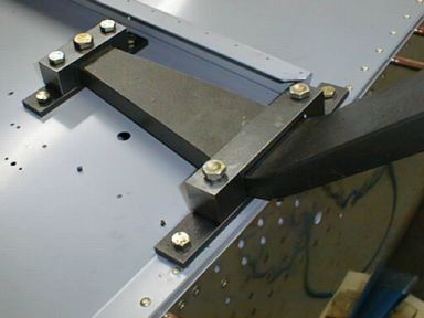 I was quite concerned about drilling all those holes through hardened steel, up to 1/4 thick, but it went quite well.
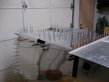 There is a complex metal fairing below the cockpit floor, between the front spar and firewall. It fairs in the landing gear leg mounting, and provides a low drag tunnel for the cooling air and engine exhaust to exit the cowling. Here you see most of the metal work clecoed in place. The ramp that smooths the exit from the cowling is not in place.
Starting to fit the landing gear legs
- Details
- Written by Kevin Horton
- Hits: 4743
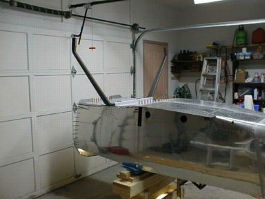 A few friends came over Saturday afternoon to help Terry and I flip the fuselage upside down. I loosely mounted the landing gear legs, strung five plumb bobs, and spent a couple of hours getting them perfectly aligned.
