Instrument Panel - Layout Changes
- Details
- Written by Kevin Horton
- Hits: 3566
I passed my proposed panel layout to a couple of coworkers to get their comments. They pointed out that I might have problems with the magnetic compass as it was pretty close to my electric Directional Gyro, and the electronic engine instruments. I posted questions on the RV-List, and the rv8 list - the answers indicated that while some people manage to get their compasses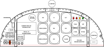 to work OK in such a location, many others have problems. Everyone who put the compass on the sides of the panel seemed to get by OK. So, I'll punt my vent to another location under the panel, and move the the compass to the right sub-panel. I moved the switches that were on the right subpanel to a second row on the left side.
I'll also lower the EIS-4000 engine monitor about an inch. That'll line up the lower right screw hole in its face with one of the screws that holds the centre portion of the instrument panel in place. It'll also make a bit more room for the tachometer and manifold pressure. My original layout has the MP gauge infringing on the flange that the instrument panel mounts too - I had planned on cutting away part of that flange but it would be better to lower the MP and tach.
Temporary Plywood Instrument Panel
- Details
- Written by Kevin Horton
- Hits: 3153
I need to start cutting holes in my instrument panel soon, so I've been messing around trying to finalize the design. I need to start running the wires for the engine instruments, but I can't do that until I get the instruments in the panel. I know where the engine instruments will be, within about an inch. I decided to cut some holes in a plywood mock-up to hold the engine instruments until I nail down exactly where they need to go. 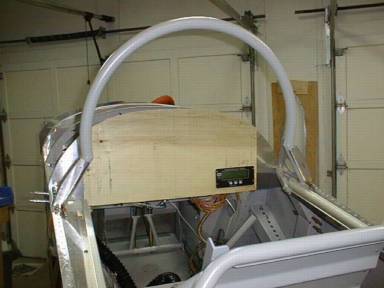 That last inch I need to sort out won't affect the wiring, so this will let me make progress. I can't really nail down the exact location of everything until I get the racks that my avionics will mount in. I'm trying to push everything as far left as I can, and the fit of the racks will determine where the rest of the stuff ends up.
This week I installed the exhaust gas temperature (EGT) probes. It took a lot of measuring to figure out where to mount the probes. They all should be the same distance from the end of the exhaust pipe, not on a curve, and not on a weld. Of course every pipe has its curves and welds in a different place, so it was a real trick to find a suitable location. I finally settled on a distance of 4 13/16 from the end. Then I had to sort out what angle to have the probes come out, so they wouldn't hit anything, or get in the way of changing spark plugs. I really gritted my teeth when I drilled the holes, because the exhaust system is pretty expensive, but it all worked out OK.
Yesterday I drilled all the holes and installed the platenuts for the various stainless steel shields that protect the rubber grommets where cables, wires, etc come through the firewall. Today I ran the cylinder head temperature and EGT wires from the EIS-4000 engine monitor though the firewall, and connected them up to the probes. I used a heat gun on each probe to make sure it worked, and that I had it wired to the correct cylinder. So far , so good.
EIS 4000 Engine Monitor
- Details
- Written by Kevin Horton
- Hits: 5663
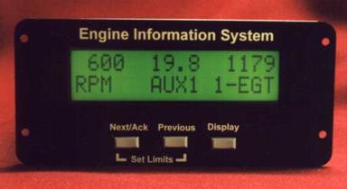 There are a lot of different options for engine instruments. Until recently, light aircraft all used analog gauges (i.e. needles on dials). Analog gauges are easy to interpret at a glance - you can quickly see where the needle ispointing, and what colour range it is in. But, you won't notice a parametre that is not in the correct range until you glance at the dials. I fly a lot of modern business jets and airliners that have various types of active annunciation of parametres that are too high or too low. This means the pilot doesn't haveto constantly scan the engine instruments, because he will be alerted whensomething happens that needs his attention. I really wanted to have somesort of similar system in my aircraft.
I decided to go with a mix of "old" analog and "new" digital engine instruments. I'll have an analog tachometer and manifold pressure gauges, as these are the primary power setting parametres, and I want to be able to check them at a glance. The rest of the engine parametres will be displayed on a Grand Rapids EIS 4000 EngineInformation System. The EIS 4000 doesn't have the prettiest display, as itis a bit cluttered. But, you can set high and low limits on each parametre, and it will flash a big red light when anything goes out of limits.
Instrument Panel - preliminary layout
- Details
- Written by Kevin Horton
- Hits: 4581
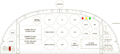 The instrument panel is probably the area where individual builders have the best chance to customize the aircraft to fit their approach to flying (and their budget). I've looked at a lot of other RV panels, searching for good and bad ideas. I have flown a fair number of different types and classes of aircraft, so I have seen quite a few different approaches. You can see a larger version of the instrument panel image in my Construction Photo Gallery.
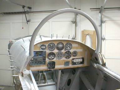
I've been fiddling around with ideas for my instrument panel for about two years now. I've been messing around on my laptop when I was on the road, and trying things out with a plywood mock-up covered in Velcro when I was home. I thought I had come up with a pretty good layout a few times, but I've always found a weakness after I ponder it for a few weeks. I think I'm finally zeroing in on a final design. The main elements of my proposed panel haven't changed for about a year now, and the details that I'm messing around with are getting smaller and smaller. I still have to get correct dimensions for a few items, so I guess I may have to still make a few adjustments if I get a nasty surprise in this area.
Mixture control linkage
- Details
- Written by Kevin Horton
- Hits: 3353
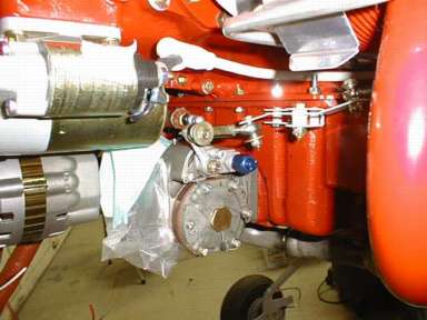 The mixture control arm on the fuel injector was mounted so that it hung below the pivot. This meant that the cable had to run below the oil sump, which put it very close to the exhaust pipes. I messed around with it, but never came up with a cable routing that I was satisfied with. I then tried putting the control arm above the pivot, which was perfect expect that would reverse the direction of the control (i.e. it would be pull for rich, rather than push for rich) It turns out that the bracket that Van sells is actually a small bracket for the throttle cable, and a bellcrank for the mixture cable. The bellcrank reverses the direction of travel of the cable so you can run it above the oil sump. It is a bit pricey, but does a good job.
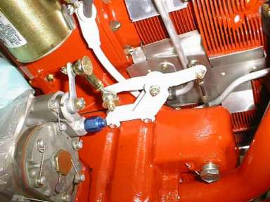 Here is another view of the bellcrank, looking up from below.
Inverted Oil System
- Details
- Written by Kevin Horton
- Hits: 8933
I started installing the inverted oil system. I have the main components of the system, but I don't have the hoses or associated hardware yet. I could have bought the official hose kit from Christen, but I couldn't stomach the $900+ price for it. Sure enough, now that I have the other hardware, and installation manual, I managed to find a list of stuff included in the hose kit. You can buy the exact same set of hoses and fittings for about $325 from Wicks or Aircraft Spruce.
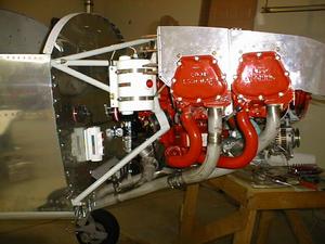 In the picture, you can see the while oil separator (large cylinder bolted to the engine mount), and the oil valve (white lump bolted to the firewall).
I've got one issue I need to deal with. I had discussed my plan to install an inverted oil system with the overhaul shop, but somehow that detail didn't make it into the quote for the overhaul, and the work didn't get done. That is as much my fault as the overhaul shop's, as I should have picked it up when I reviewed the quote. Anyway, when the inverted oil kit finally showed up (it was back ordered for over two months), and I studied the installation manual, I found that my engine model does need a sump mod. I'm going to have to remove the sump and get a boss welded on to take a hose that provides oil to the inverted oil system.
