Induction Air for IO-360A
- Details
- Written by Kevin Horton
- Hits: 3773
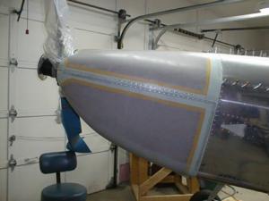
The IO-360A series have the fuel injection servo mounted on the forward face of the oil sump, rather than on the bottom. This allowed Van to design an induction air system that has an air filter on the baffle floor ahead of the left cylinders, and a "snorkel" that routes the air to the fuel injection servo.
 The fibreglas snorkel must be trimmed to length at the top - the idea is to have it just clear the starter, so that it is as high and as aft as possible, to make sure there is adequate clearance between the snorkel and the lower cowling.
Read on for more.
Baffles, induction air
- Details
- Written by Kevin Horton
- Hits: 3204
I'm making slow progress on the baffles. I've got the horizontal floor at the front on the left side in the correct position, but I had to remake an attach bracket on the inboard side twice to get the front of the floor at the correct height.
Then I started fitting the "snorkel" that takes induction air from a filter on the floor in front of the left cylinders and snakes it down to go into the fuel injection servo mounted on the front of the oil sump. I did a lot of trimming on the snorkel today, but I've still got a bit more to go before I'm done.
I learned on thing when fitting the snorkel - Do not trim the front or outboard edges of the floor in front of the left cylinders! I had trimmed the front edge a tiny bit, as it was interfering with the aft edge of the air inlet on the lower cowl. Well, you need every square inch of the that floor to mount the air filter (assuming you have an IO-360A, and are using the snorkel). I have just enough metal left (I think - if not, I'll rivet on an extension). I ended up trimming the aft edge of the air inlet on the cowl to get the clearance I need so I could install the remove the lower cowl without it getting hung up on that floor.
Site update
- Details
- Written by Kevin Horton
- Hits: 4057
Site Status Update - I've got all the construction status pages from the old RV-8 web site copied over to this new site. I've also brought over all the Flight Test Links. I've started bringing the RV Links, but it will probably take a couple of weeks of spare time (i.e. when I'm too tired to be building the aircraft) to get them all copied over. Then I'll be working on fine tuning the visual presentation of the site.
Site Features - The software that is running this new site has some interesting features.
- Search Engine - There is a pretty good search function built it, available from the top of every page. If you type one word, it will find every instance of that word. If you type several words, it assumes that it is a phrase. If you put commas between words, it assumes each word is a search term and it looks for pages that have all those words on them.
- Comments - You can leave comments on pretty much any page.
- Submit Links - Visitors can submit links for the Links page.
- User Preferences - If you log in, you have the option to set a number of user preferences, including different visual presentations, which pieces of info to display, etc.
The big reason I am changing the site is that the old one had become too much work to update. I kept entering status updates on the Status Page, but I had to manually move old info to the appropriate pages, which took a lot of work. All I have to do now is write the original item and the Geeklog software takes care of everything else automatically. So I should be able to keep the site more up to date.
Blasted baffles
- Details
- Written by Kevin Horton
- Hits: 3896
I've been beavering away on the cooling baffles the last few nights. I've been making progress, but I've still got a lot of messing around to do. I don't have nearly as much clearance between the left side baffles and the cowl as I would like, so I am agonizing over whether I should just press on or if I need to do some sort of major cowl mod. I think this issue arrises from my desire to fit the upper cowl fairly low to allow for eventual engine sagging in the mounts.
I've got the baffles trimmed a the sides and back - tonight I started working on the horizontal floor at the front left side. This piece of horizontal floor has to fit closely to several other baffle pieces, as well as match up to the bottom of the air inlet in the cowling. And it holds the filter for the induction air. The bottom line is this piece has got to be trimmed and fitted to match up several other parts, and you can't tell how much to trim it until you get it in place, and you can't get it in place until you trim it. Great fun.
I had a great plan to mount my oil cooler on the back left side of the engine baffles, (I wanted to copy Randy Lervold's oil cooler mount and I managed to acquire some aluminum channel to fabricate the mount. Well, now that I've got the rear baffles trimmed to fit under the cowling, I discovered that things are very different with my IO-360A than they are with Randy's O-360. The oil cooler will have to go a bit lower and further inboard than I expected, and it will hit the engine mount if I use the aluminum channel I've got. So, I need to rethink the whole oil cooler mount concept.
Cowl trial fit and hinge pins
- Details
- Written by Kevin Horton
- Hits: 4345
It took forever for the Proseal under the cowl hinges to cure, so I couldn't do a trial fit on the cowl until today. I was worried that the thickness of the Proseal would screw up the fit, but it went on perfectly.
 I bent the forward end of the hinge pins so they wrap around the shank of a countersunk #8 screw, which will go into a platenut to secure the hing pins. I'll cover the screws with nice stainless steel covers made by Dale Lamport, a prolific local RV builder. Thanks Dale!
Oil Filler Door
- Details
- Written by Kevin Horton
- Hits: 4289
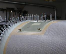
I've been messing around with the oil filler door the last two days. It is a simple piece of flat fibreglas, hinged at the top with a piano hinge, and with two wingnut CamLoc fasteners at the bottom corners.  It all went well enough, once I shaved away a bit of fibreglas to allow the male part to go deeper into the receptacle. The door is all ready to rivet to the hinge, but I think I'll hold off on that a bit, the hinge pin can't be removed once the hinge is riveted in place - I would need to drill out the rivets if I need to remove teh door for some reason.
