Spinner
- Details
- Written by Kevin Horton
- Hits: 4294
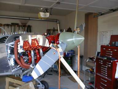
Propeller and spinner - The prop spinner comes as a simple fibreglas dome, which can be used on a variety of fixed-pitch and constant-speed props. The builder must make cutouts in the spinner so it can fit over the blades. The blades on a constant speed prop twist through quite a range of angles, so the cutout in the must be big enough to ensure there is clearance between the blades and spinner.
 I strapped some pieces of wood to the back side of the prop blades so I could twist them through their range of motion as I fitted the spinner. I wasn't as careful as I should have been, and the blades contacted the spinner in two places as I twisted them. I have to remove some of the paint and then see whether I scratched the aluminum. If so, I'll polish out the scratches to be sure there aren't any stress concentrations, using Hartzell's guidelines.
I've still got to finish installing the little metal plates that fill the area behind the prop blades, install the nutplates that the spinner screws go into etc, but I'll do all that stuff once its too cold to do fibreglas work.
Got the replacement wing tip covers
- Details
- Written by Kevin Horton
- Hits: 3403
Mounted the prop
- Details
- Written by Kevin Horton
- Hits: 2778
I borrowed an engine stand to support the weight of the prop while I mounted it to the crank.


Enclosed Wingtip Lights
- Details
- Written by Kevin Horton
- Hits: 5000
Enclosed wing tip lights

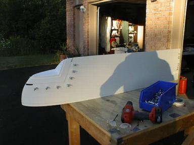
Last weekend I started modifying the wing tips to add a plastic covered recess to hide the nav and strobe lights from the breeze. The picture shows where I removed a section of the wing tip so I could insert a ready-made piece of fibreglas to take a clear plastic cover.
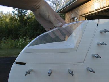
I got the fibreglas inserts clecoed in place on both tips, and I started trimming the plastic covers, but I decided to get the covers replaced, as the inside surface of both of them had numerous, noticeable blemishes. It looked like there had been a large quantity of grit on the mold that the covers were formed over - the blemishes were very noticeable in the sunlight. The vendor offered to replace the lens, so I am waiting for the new ones to arrive before pressing on.
 Here you see the clear plastic cover that goes on the recess. I'll attack the wing tips again after I get the new plastic covers from the vendor.
Updated instrument panel design
- Details
- Written by Kevin Horton
- Hits: 3175
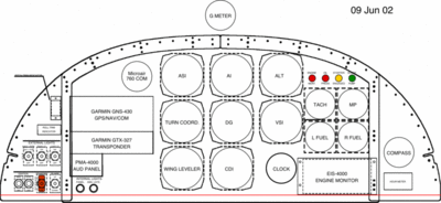
I updated the  instrument panel system to reflect the list of avionics I ordered. I also moved the magnetic compass to the far right side of panel to get it away from the gyros. You can see the various iterations of the instrument panel design in my Instrument Panel Layout Gallery.
I added a low oil pressure red light, which will be on its own pressure switch to back up the EIS 4000 low oil pressure annunciation. If only one sensor indicates low oil pressure, I'll know that it is a sensor problem. If they both indicate low pressure I'll know I have a real problem.
I moved many switches to the left side, so they can be operated with the left hand, as the right hand will be on the control stick.
I ordered the avionics
- Details
- Written by Kevin Horton
- Hits: 3310
In the last few days I made the round holes for the compass and Microair Com, and the rectangular hole for the hourmeter. Then I put the panel back in the aircraft temporaily. Today I did the wiring for the analog round tachometer (as opposed to the digital tachometer which is part of the EIS 4000 Engine Instrument System).
I ordered my avionics from Stark Avionics to get a quote on my avionics package. John Stark seems to have the best avionics prices around, and he has a reputation of being easy to deal with, and providing good service. Everything is ready to ship, except that the Microair com is back ordered.
