Listened to ATIS!
- Details
- Written by Kevin Horton
- Hits: 3055
I need to change the wire that goes between the audio panel and the rear seat headset jacks, as the current wire isn't long enough (I screwed up). I was thinking about doing the job myself, but the wires are soldered to the connector that attaches to the back of the audio panel, and I don't trust my soldering. So, I thought I would replace the whole connector with one that uses crimp-on pins, as I have the right tool to do that.
Last night I took a closer look at how much work would be required to rewire that whole connector, and I decided to ask my local avionics shop how much it would cost to have them solder the longer wire to the existing connector. It shouldn't be too difficult a job for someone who is comfortable soldering small connectors.
I decided I should do a complete functional check of the harness as it is now, so I know if there are any other issues that need sorting out when I go to the avionics shop.
Last week I had the local avionics shop install 90° connectors on one end of the four coax cables that attach to the GNS-430. This morning I ran the coax cable from the GNS-430, under the floor to the area of the antenna for Com 1. Tonight I put the coax connector on the antenna end, and plugged it in. Then I temporarily installed the audio panel wiring harness, plugged in my headset, and powered up the avionics. Hmm - the intercom works, but I can't hear anything on the radio. Oh oh.
Much scratching of head. Suddenly I realized that I hadn't attached the Molex connector that goes between the audio panel wiring harness and the GNS-430 wiring harness. I turned off the power, plugged in that Molex connector, and powered everything back up. Bingo - I could hear the ATIS from the Ottawa International Airport. Wow!
Tomorrow I'll install the Microair 760 (Com 2), and hook it up to the same antenna to be sure that function works. Then I'll track down a hand-held VHF radio so I can try transmitting from each Com to be sure that works.
Slow week
- Details
- Written by Kevin Horton
- Hits: 2910
This has been a slow week as far as progress goes. Lots of flailing around, but a depressing small amount of actual progress.
First, I ended up spending a bunch of time helping Terry reorganize the office. It needed doing, but it ate an evening. Then, I spent a huge amount of time drilling holes in bulkheads, and running the wires for the pitch trim system. I also started gathering up wires into bundles, and drilling bolt holes to take Adel clamps to secure the bundles.
Then I spent way too long agonizing over where to put the GPS antenna. I had planned to put it on the glareshield, just above the instrument panel. But I realized that there wasn't going to be much room to run the coax cable up between the instruments to get to the bottom of the antenna. It would have worked if I hadn't had to jam all the instruments to closely together. I finally decided that I needed to give up on the glareshield and put the antenna back behind the rear seat. It'll still be underneath the canopy, so there won't be any drag. Today I drilled the holes where the coax will go from the GNS-430 to the antenna. And I spent a bunch of time drawing up notes to help when I rewire one of the audio panel connectors so I can extend the rear seat head set jack wires.
Stolen Engine in MN
- Details
- Written by Kevin Horton
- Hits: 3191
The following message was posted on the RV-List. Please be on the look out for a stolen engine
--> RV-List message posted by: "Doug Weiler"
Fellow Listers:
I got a call yesterday from a Bruce Anderson of Buffalo, MN. He is requesting all EAA'ers and homebuilders to be on the lookout for a stolen engine. He had temporarily tied down his nearly completed Glastar at the Buffalo, MN airport. Last Saturday night, persons unknown removed the 0-360 Lycoming engine and stole it. It's hard to believe that something like this could happen among aviators, but apparently it did. Attached is more information. Please be on the lookout for any suspicious engines for sale at bargain prices.
Bruce was not insured and is very upset as you can imagine. All local EAA chapters, engine shops, FBOs, salvage yards, etc have been notified. Please contact the Buffalo police (763-682-5976) if you have any information on this robbery.
Thanks
Doug Weiler
For detailed information, please go to this website:
Navaid, trim wiring, coax and computer problems
- Details
- Written by Kevin Horton
- Hits: 3813
This has been one of those weeks where I seemed to flail away, but not accomplish as much as I hoped. My first task of the week was to do the wiring for the Navaid wing leveler. Simple enough, except that I wanted to be able to disconnect it quickly if it does something strange. I‚'ve got a red button on the stick grip which will be the disconnect switch. To further complicate things, that red button will also disconnect the electric pitch and roll trim, just in case they ever have a run away. And to top it all off, the trims are powered from the essential bus, but the Navaid is powered from the main bus, as I am willing to do without it if I ever have an alternator failure and have to shed some power users.
So, my wiring diagram has a two pole disconnect relay, controlled by the disconnect switch on the stick. One pole of the relay controls the trim power, and the other pole controls the Navaid power. However, I had actually purchased this two pole relay. I had expected that it would be easy to find at the local electronics supply place that I frequent. Sure enough, they had a suitable relay, but this relay needed to fit into a socket, and the only sockets they had were designed to be soldered to printed circuit boards.
This set me off on a several hour search through paper and on-line catalogs. I was able to determine that NTE, the relay manufacturer, made several different kinds of sockets, and one of them was sure to be correct, but the descriptions were so cryptic that I couldn‚'t be sure which one I needed. I finally had a bright idea and searched their list of distributors, which highlighted a local distributor that I wasn‚'t aware of. A quick visit to Gervais Electronics proved fruitful, as they had exactly the relay and socket I needed.
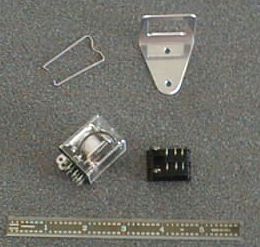 If anyone else needs a small, low power two pole relay and socket, you might try the NTE R14-11D10-12 relay, and the NTE R95-111 socket. This photo shows the relay, socket, mounting bracket to hold the socket, and the wire that secures the relay to the socket.
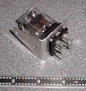 Thursday I fabricated a mount to hold the relay socket, and yesterday I soldered the various wires to the socket, installed the relay and finished wiring the Navaid (except for the input from the GPS). I threw the switches, and everything worked, except the Navaid servo turned the wrong way - i.e. it moved the stick left when I commanded a right turn. This issue is covered in the Navaid manual - depending on the details of any individual installation, the servo direction may need to be reversed by switching some wires inside the servo. Today I pulled the servo cover, got out the soldering iron and swapped two pairs of wires. Now it works properly. I will have to go through a phase of setting system gains, etc, but I‚'ll sort that out once I get flying. I don‚'t plan to have the servo connected to the stick for the first flights, as that means one less failure mode to worry about.
Today I started on the pitch trim wiring. I thought I knew where I wanted to put the rear seat pitch trim switch, but I finally realized today that my originally planned location would put it too far aft, which would make it difficult to use. I studied the cockpit, and saw that the best location was just ahead of the rear seat throttle lever. There was just enough room to get a switch in there, if I could find a single pole switch. I had a double pole switch I was planning on using, but I was only going to be using one of the poles. However it was too wide to fit - I needed a single pole switch that was spring loaded each way from centre. Another big search through web catalogs and I finally found the switch I needed, and a distributor who sells it.
Many months ago I spent hours fighting with the rear seat throttle as I installed it, and I dreaded the day I would ever have to do it again. Well, I couldn't drill the hole for the rear seat trim switch without removing the rear seat throttle, so I had to pull it out today :(. It took about an hour to get it out and back in again, but it actually went much better than the first time I did it.
I also trimmed the coax cable for the transponder antenna, installed the connector and hooked it up.
And to top everything off, our main computer decided to have a hard drive problem when I attempted to download the photos I took. So no pictures tonight (pictures added on 29 Mar 03). The hard drive utility is running now, but it doesn't look good. I think I'll have to reformat the hard drive and restore everything from the backups. Oh joy.
Rudder Pedal Mod - Fix for Uncommanded Brake Application
- Details
- Written by Kevin Horton
- Hits: 3547
The rudder pedals are designed so that the ball of the foot rests on a flat part of metal, which is above where the pedals pivot to apply the brakes. Thus any pressure on the rudder pedal will necessarily put pressure on the brakes, even if the pilot is careful to rest his foot on the bottom part of the flat area.
RV-8 builder Jeff Jasinsky designed extensions to allow the heel of the foot to apply rudder pressure, which is below where the brake portion pivots. This allows rudder to be applied without applying any brake pressure. Randy Lervold has pictures and a description on his web site.
I plan to mod my brake pedals like this.
Wing Leveler Servo Mount
- Details
- Written by Kevin Horton
- Hits: 5430
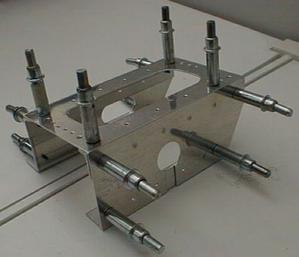 I focused on the wing leveler servo mount this weekend. It took a bit of trial and error, but I think that it will work out nicely. I started off with the measurements that I got from Ray Lynn, but they seemed to put the pushrod right up against the bottom side of the fore-aft reinforcing angle that goes from the top of the wing spar carry through to the landing gear box. I think part of the discrepancy is that his measurements likely are to the top of the spacer that goes under the mounting tabs on the servo, whereas I measured to the top of the deck only. I ended up lowering the mounting tray deck by 5/16 inch. That will let me use the third hole from the pivot in the servo arm if required to get more pushrod travel, and I can put spacers under the servo mounting tabs if I need to raise it to get more clearance to the rudder cable.
The first picture shows the rear side of the tray. I've already got a bunch of wires that will have to run fore and aft under the tray, so I needed to allow the tray to be installed without disturbing them. I plan to rivet the two pieces of angle to the floor first, using blind rivets. The two vertical flat pieces on the front and rear faces have holes in them to allow the wiring bundle to pass through, with slots that go all the way to the bottom so the tray can be slipped over the wires.
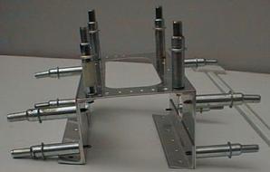 I pondered how to get the trays in place for quite awhile. I thought I might have to assemble them in place, which would be a real trick. I eventually decided I could rivet everything together but the two angles at the bottom, then use screws and nutplates on the angles to fasten the vertical pieces to them.
The second picture shows the tray from the inboard end. You can see the two pieces of angle that attach the whole works to the floor. Those two pieces of angle had to be squeezed a bit to make the angle less than 90°, as the floor slopes up.
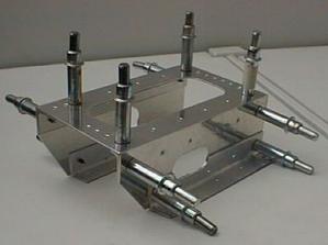 The last shot shows the tray looking from the front. The outboard end (left in the picture) is cut away at the bottom, as it has to go over a piece of angle that sits at the outboard edge of the floor.
I'll prime the tray parts once it warms up enough to paint outside in the driveway, then I'll assemble and install it.
Larger versions of these photos can be seen in the Construction Photo Gallery.
