Powered up the avionics stack
- Details
- Written by Kevin Horton
- Hits: 3032
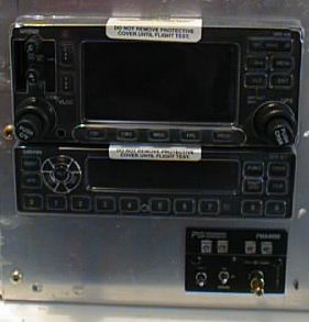 I was on the road until late Thursday evening, I flew Friday evening, and Terry got home Friday night for a day and a half, then she was going back on the road again. So, I didn't get any work done from Wednesday, until early this afternoon after Terry headed back on the road.
This afternoon I put the holes in the panel where the knobs, switches and buttons of the intercom panel stick through the instrument panel. I didn't take a close enough look at the right side of the intercom box before I put the holes in the panel. It turned out that there is a small screw whose head is sticking out the right side of the intercom box, and it interferes with the piece of angle that attaches the avionics trays to the panel. I had to remove that screw to allow me to fit the intercom box to the panel, but that isn't an acceptable permanent fix. I'll have to grind a piece out of the angle to make room for the screw head.
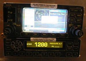 Next, I decided to power up the GNS-430 and GTX-327 to make sure they worked. Garmin's warrantee is only good for one year from the date of purchase, so I need to know soon whether these two boxes are OK.
I spent a while studying the wiring diagrams in the Installation Manuals, then I got out the multimeter to be sure the power lines in the wiring harness weren't shorted to any of the other pins in the connectors. If power were to go to the wrong pins that could cause a lot of damage.
I've got a small 12 volt power supply that was made by an unknown RV builder a few years ago. He passed it onto to another builder, who passed it on to me. I'll give it to someone else once I'm done with it. I was very relieved, and very excited to see the displays come to life once I connected the power supply to the wiring harness and turned on the avionics. No smoke escaped from the boxes (it is common knowledge that avionics are powered by smoke, as evidenced by the fact that if the smoke ever leaks out of the avionics box, it will stop working).
It was very neat to see the avionics come to life! I also plugged the CDI into the wiring harness, and it did all the right things as the GNS-430 went through its self test sequence.
Rack fitted to instrument panel
- Details
- Written by Kevin Horton
- Hits: 3248
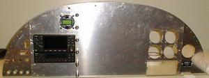 Tonight I cleaned up the last bit around the big hole in the instrument panel, then spent a while trying to figure out why it was so difficult to get the GNS-430 to slip back all the way info the rack. You have to slip the two avionics boxes almost all the way into position, then stick an Allen wrench into a small hole in the front of the box and turn a Rube Goldberg type device that pulls the box back to force it to engage al the connects at the back. The GTX-327 transponder slips into place nicely, but I had a hard time getting the GNS-430 to follow suit. I never figured out exactly what is going on, but I eventually managed to get the proper sequence of jiggling, lifting, twisting and pushing to make it happen repeatably.
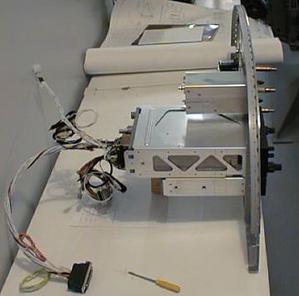 Once I was certain that I could actually get the boxes to slip into the rack with the right side clamped in position on the instrument panel, I drilled the holes that fix the location of the right side angle to the panel.
I think I'll be tied up most of the time until Sunday now, but my next task is to fit the intercom to the panel. Then I'll look at moving the errant feeder line that supplies power to the main bus.
Rack progress
- Details
- Written by Kevin Horton
- Hits: 2607
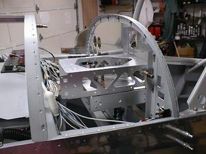 Terry ended up leaving today for several days of training, so I'm going to try to hit the project hard while she is gone. I tried to get the two avionics racks up behind the instrument panel as a unit tonight, but there was not enough clearance to slip them in place from the bottom. I had them carefully clamped together in perfect alignment, so I didn't want to separate them. I finally resigned myself to unclecoing the upper forward skin so I could go in from the top.
It turns out that the wiring bundle I was worried about isn't a problem, but the feeder to the main bus has to be rerouted. The good news is I think there is enough slack in that feeder that I can move it out of the way without having to make a longer one.
Next I pulled the whole instrument panel out, including the left and right subpanels, carefully clamped the rack in place, and marked where the screw holes go on the left side. I was able to slip the GNS-430 into the rack, and it looks like the big hole in the panel will work out great once I remove just a bit more material on the bottom. That's tomorrows's job.
Avionics Stack Hole in Instrument Panel
- Details
- Written by Kevin Horton
- Hits: 3679
Yesterday afternoon I attacked the task of putting a big hole in the instrument panel to accept the avionics stack. I've discovered that the easiest way to make big holes is to use a large bit in a drill press to make a series of holes close to the intended line. Then it is a fairly easy task to use a nibbler and a large file to finish the job.
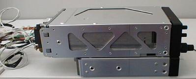 Today I slipped the Garmin GNS-430 GPS/Nav/Com and GTX-327 Transponder into the trays and stacked them on top of each other on the bench. I carefully lined them up so the face of both were lined up with each other, and then marked a reference line on each side of the trays. The reference line gives me a fighting chance of ending up with the face of the two boxes even with each other. It also gives me a reference to measure to when attempting to mount the racks so the back edge of the protruding part of the avionics box is almost touching the instrument panel.
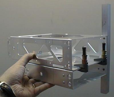 Next I clamped the two racks together, clamped the angle that goes on the right side in place, and marked the location of the holes for the screws that attach the racks to the angle. There are little "feet" on the racks that keep them a little bit apart, so I found that I needed to slide a piece of 0.040" sheet in between the two racks when I clamped them to avoid deforming them.
The angle that goes on the left side of the racks is already attached to the back side of the left sub-panel in the aircraft. So my next trick will be to figure out a way to hold the racks in position against that left side angle so I can mark the location of those holes. Then I'll drill the right angle to the instrument panel. I'll be narrowing the face of the angle that goes against the instrument panel from 0.75" to 0.50".
Instrument Panel Layout Adjustments
- Details
- Written by Kevin Horton
- Hits: 2981
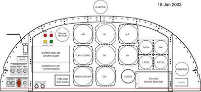
I have to order a few odds and ends before I can finish up the last oil cooler hose, or put the top on the cooling plenum. Last week I completed a couple of little things that had been waiting for parts. I'll work on the instrument panel and avionics while I build up a large enough list of parts to make it worthwhile putting in an order.
I spent a couple of evenings this week reading the avionics installation manuals. to make sure I had a handle on all the issues. Thursday night I unwrapped the avionics and took a closer look. I had thought that the face of all avionics would in the same plane (i.e. they would be the same distance from the face of the instrument panel). Well, once I took a closer look at everything I realized that the round Microair com and the intercom panel would be essentially flush with the instrument panel, but the GPS/Nav/Com and the transponder would stick out back of the panel a fair bit. I tried sitting the avionics on my desk, with some pieces of wood between them to put them the intended distance apart, and I realized that the top of the intercom panel would be sort of hidden under the bottom of the transponder, making it difficult to see the little buttons that select the functions. So, I needed to make yet another adjustment to the instrument panel layout.
I spent some time yesterday morning looking at my options. I couldn't move the intercom panel any lower, as it would then be too close to the lighting rheostats. I decided the best solution was to move the intercom panel down and to the right. This let me lower the GPS/Nav/Com and transponder a bit too, making more room above them. I moved the four annunciator lights from the right side of the panel to the left side, as I realized that my focus will be more on the left side of the panel than the right, as the moving map GPS is on the left. Then engine instruments are on the right, but if any parametre goes out of limits, the EIS-4000 engine monitor will illuminate a red light in the annunciator group to catch my attention.
You can see the various iterations of the instrument panel design in my Instrument Panel Layout Gallery
Request for in-flight engine power data
- Details
- Written by Kevin Horton
- Hits: 4033
