GPS Antenna
- Details
- Written by Kevin Horton
- Hits: 3630
Spring has finally arrived, so there were lots of start of the year projects to do around the house, which has slowed progress on the project.
 I mounted the ELT antenna, routed the coax to the antenna, and carved a hole in the instrument panel for the ELT remote control head. It came with a long phone cord which allows the ELT and the remote control head to communicate. The phone cord was about 5 feet too long, so I purchased a cheap Radio Shack phone modular plug tool, and shortened the cord. I was amazed at how well a plastic tool that costs less than $10 worked.
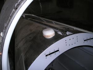
Today I put the partially finished sliding canopy back on the aircraft so I could see how much room there was to mount the GPS antenna. It turns out there is lots of room, as long as it is placed so as to avoid the slider that hooks on the centre canopy track. The canopy framework slides over top of the GPS antenna with lots of room to spare. The antenna must be mounted fairly close to the canopy rail, to keep it well inboard of where the shoulder harness will go.
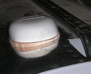 The bottom of the antenna is flat, and the fuselage skin is curved, so I needed something to fill in the curved space. I decided to use a piece of balsa wood. I'll cover it with some West Systems epoxy to give it some strength and to smooth out the surface. I was at a bit of a loss how to get the curved surface on the bottom of the balsa, but I eventually taped a piece of coarse emery cloth on the rear fuselage, and used some double-sided tape to attach the balsa to a the thick doubler that Garmin provides to be used with the antenna. It took a few minutes, and made a real mess of sawdust, but the piece now fits quite well. I'll cover the area with electrical tape, wax the bottom of the antenna and the electrical tape, and slather the area with epoxy and filler to fill in the last few gaps.
I also fabricated the coax cables for the GPS antenna and for the glideslope.
ELT
- Details
- Written by Kevin Horton
- Hits: 4168
 I ended up spending several days in Montreal last week, so that slowed things down. I finished installing the Navaid servo mount - I just need to purchase a long flat head screw to hold an Adel clamp that will hold the wire bundle that goes under the mount.
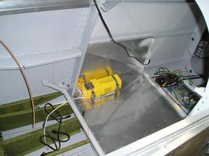
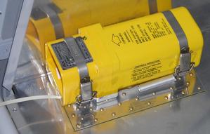 Now I'm working on the Emergency Locator Transmitter (ELT) installation. I've got an ACK E-01 ELT. I selected this model as it gets good reviews for being trouble-free, and it uses regular D-cell batteries, rather than some expensive special one-off battery like many ELTs. The ELT mounts in the front right corner of the aft baggage area. According to the Canadian requirements, the mount must be able to withstand 45g in the forward direction, so I did a few quick sums that convinced me that I needed to put a doubler in this area to be sure the floor wouldn't buckle.
There is no good place to put the antenna on an RV-8 that meets all the "regulatory requirements". They want the antenna mounted as far aft as possible, and they want the position to "ensure essentially omni-directional radiation characteristics when the aircraft is in its normal ground or water attitude". I have no idea why they are worried about how it works in the "normal ground or water attitude". If the aircraft is still on its wheels after an accident, then I can just open up the baggage compartment and attach the ELT's portable antenna and start transmitting. If the aircraft is no longer on its wheels there is no way to predict what attitude it will be in.
The RV-8 canopy slides over the whole aft fuselage when it opens, so that area is out of the question. The windscreen and forward baggage door pretty much rule out the forward fuselage, and I don't want to be staring at the ELT antenna right in front of the windscreen anyway. Some guys mount the antenna horizontally under the fibreglas empennage fairing. Some guys put the antenna in the fibreglas wingtip. Many others put it on the RH arm rest next to the rear seat - this is the option I am using. The antenna will be quite close to a fuselage bulkhead, and the skin, so it won't have a perfect antenna pattern. But I'll use the portable antenna after an accident. If am not in good enough shape to get at the ELT then I probably won't survive until the rescuers get there anyway, so the whole point is moot.
Yet Another RV-10 Update
- Details
- Written by Kevin Horton
- Hits: 4259
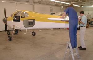 Progress on the RV-10 is going fast and furious at Vans. Yesterday they updated the RV-10 Info Page to show pictures of them installing the horizontal tail. The fact that they had to stand on step ladders illustrates how much bigger it is than the current RV models.
RV-8 Fairings from Fairings-Etc.
- Details
- Written by Kevin Horton
- Hits: 3458
Upper gear leg and wheel pant fairings are now available for the RV-8 from Fairings-Etc.
New RV-10 Update on Van's Web Site
- Details
- Written by Kevin Horton
- Hits: 3609
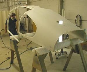 There is a new RV-10 update posted on Van's web site. They have recieved the fibreglas cabin roof, and are installing it.
Navaid Mount Trials and Tribulations
- Details
- Written by Kevin Horton
- Hits: 4502
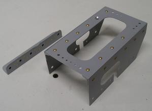 The weather on Sunday was finally warm enough that I could prime the parts for the Navaid servo mount outside. Monday I riveted the various parts together, and yesterday I started trying to install the two pieces of angle that will be blind riveted to the floor so that the mount can be screwed to them.
I sure wish I had spent another 30 seconds thinking about how I would install the brackets before I drilled all the holes. I spent quite awhile pondering the details of the servo mount, thinking about the assembly sequence, figuring out which parts could be riveted with hard rivets, which ones would need blind rivets, and which parts needed screws so they could be disassembled later. I eventually decided that the two angles at the bottom would need to be installed first, and that the rest of the mount would be screwed to those two angles. That would allow the mount to be assembled around the wire bundles that are already installed in that area.
 But, when I went to install the two angles, I realized that I had installed the nut plates so that they stuck out and got in the way of where the blind rivets went. Everything would have been fine if I had staggered the holes so they didn't line up, but that detail escaped me until it was too late. I had to either find a way to install it as is, or spend hours making a new mount.
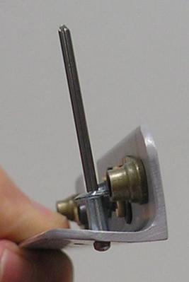
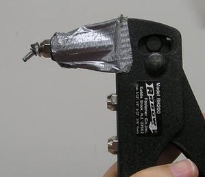 I ended up making a small steel wedge shaped piece, with a hole in it for the nail of the blind rivet. This allows the nail to be bent, so the riveter will clear the nut plate.
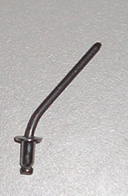 The blind rivets needed a pretty significant bend to clear the nut plate.
I got the front angle installed today, but I need a different riveter to get at the back one.
