Ariel Arielly's Electrical System Diagrams
- Details
- Written by Kevin Horton
- Hits: 3731
RV-8A builder Ariel Arielly from Israel needed a place to post his electrical system drawings. So I offered space on my web site. If you have OrCAD, you want the version in OrCAD format (76kb). Otherwise you want the version in Microsoft Word (RTF) format (333kb). Please note that both files were zipped, so you will need WinZip or equivalent to decompress them.
Back from Oshkosh
- Details
- Written by Kevin Horton
- Hits: 3388
I got back from Oshkosh Friday afternoon. It was a great trip. Monday evening I got an RV-6 flight with Mark Nielsen from Green Bay - I wanted to evaluate the Dynon EFIS that Mark had recently installed. I've got a few suggestions for improvements that I will send to Dynon, but I saw enough to confirm my decision to buy one and test it.
I'm not sure how many RVs were at OSH, but the large RV parking area was almost full. There were certainly enough RVs that I didn't take the time to study each one - I concentrated on the RV-8s and -8As. There were several exceptionally nice aircraft, and I learned a few things from inspecting them, and talking to the builders. I attended gatherings of RV-8/8A builders in the Theater in the Woods on Tuesday and Thursday - it was nice to be able to put a face on some of the people that I have been e-mailing. Every time I meet RV builders I am struck by what a great bunch of people they are. I don't know why, but there seem to be very, very few idiots, flaming A-holes, pompous jerks or other unpleasant types.
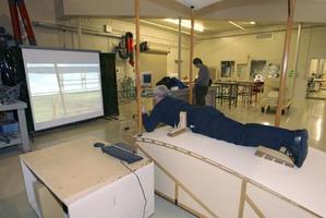 Wright Flyer Simulator - As part of EAA's Countdown to Kittyhawk celebration of the 100th anniversary of the Wright Brothers' first flights, there were several Wright Flyer simulators at Oshkosh. They had a flat area to lay on, a hip cradle for lateral control and a lever for pitch control, just like the original Wright Flyer. The view ahead, including the biplane canard elevators, was projected on a large screen in front. It was quite difficult to fly, and many people crashed within 15 seconds of lift-off, but a small number of young kids did very well. Light weight helps I guess :)
The performance was quite poor (just like the real thing), and it was not possible to climb out of ground effect without stalling. The simulation appeared to be on some sort of military installation, with lots of buildings and trees. The optimum pitch attitude put the lower plane of the biplane canard on the horizon. So obstacle avoidance was a real problem. It was difficult to keep it flying in a straight line, and the screen had a field of view of about 10 degrees, so the unplanned turns would bring new obstacles into view.
Lateral control was a real issue - the aircraft was quite slow to respond to lateral control input (you slid sideways in the hip cradle to make a lateral control input).
I did two goes at the simulator. I got into a lateral pilot induced oscillation on the first one, and eventually hit a tree that came into view during a turn. The second attempt went much better, but it too eventually ended with a collision with a tree.
Off to Oshkosh
- Details
- Written by Kevin Horton
- Hits: 3243
I'm leaving for the EAA Fly-In at Oshkosh, WI tomorrow. I'll take the airlines to Chicago, rent a car and drive to WI. I'll be staying with a sister-in-law between Green Bay and Oshkosh. I'll be at the Fly-In for three days and come back home on Friday.
I'm looking forward to meeting other builders and seeing a bunch of completed aircraft. Other RV-8 builders have organized get-togethers in the Theatre in the Woods at 9 AM on Tuesday, Thursday and Saturday. I should make the first two of these gatherings.
I made progress on the canopy skirt this week - the right aft part is looking promising enough that I started the process to make a new left aft portion. I also got a good start at fitting the fibreglas rudder bottom fairing. And I trimmed the rear seat back so it doesn't rub on the passenger shoulder harness.
Canopy Skirt - Small Steps
- Details
- Written by Kevin Horton
- Hits: 3298
We've had company visiting for a few days, so I haven't gotten any work done on the project since the middle of last week.
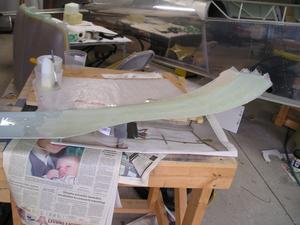
The canopy skirt has been a real bear to fit. The first attempt, many, many months ago, caused me to give up in disgust as I could not get a good fit on the rear portion. The crux of the problem is that there is quite a bit of aircraft to aircraft variation in the canopy shape (it is free blown, so every canopy is a bit different), and how the builder fits the canopy to the aircraft. But the skirt is made in a mold, designed to fit some mythical nominal aircraft. There is an angled flange at the top of the canopy skirt, where it fits against the bottom part of the canopy. On my aircraft, the angle on the flange is too great, which forces the bottom part of the skirt away from the fuselage skin.
I tried Plan B recently, which involved filling in the holes I drilled in the aft part of the skirt, and redrilling them. At first it looked like I had an acceptable fit, but in the end I was still unsatisfied, as there were several areas where I could still slip my fingers between the bottom of the skirt and the fuselage. Plan C involved using a heat gun to try to soften the fibreglas so I could change the angle on the flange at the top of the skirt. This didn't work, as it seems that the material the skirt is made from must get really, really hot before it becomes soft. I ended up turning some parts of the skirt brown from the heat, and causing some delamination, but I still couldn't change the angle of the flange.
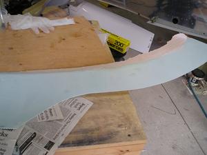 So I decided that I needed to make a new aft skirt, that fit my aircraft. I covered the lower part of the right side of the canopy with electrical tape, and put a bunch of wax paper on the fuselage. Then I put some filler on the canopy skirt flange where it met up with the canopy. I taped the canopy skirt in place, making sure it matched up against the fuselage. The filler on the flange hardened, giving me a one-sided mold that had the flange at the right angle. The filler didn't stick to the electrical tape, so I was able to pop the skirt right off and clean it up.
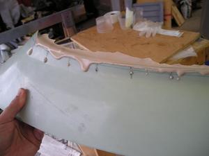
Plan D - I put electrical tape on the inside of the skirt, and laid up one layer of fibreglas cloth on it. This didn't work, as the electrical tape pulled free from the skirt as the fibreglas resin cured, so the new layer had some large, weird lumps in it. Plus the single layer was really too flexible to work with. One for the trash can.
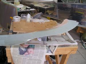 Plan E - I put clear packing tape on the inside of the skirt, and laid up two layers of 2" wide fibreglas cloth. I used the narrow strips of cloth, as I found it too difficult to work with a large area of cloth the first time I did this.
Plan E looks promising. I popped the new skirt off, and it fits very nicely. Tonight I cut the aft portion off the original skirt, and bonded it to the new skirt with a 2" strip of fibreglas. Tomorrow I'll check the result then lay up another couple of layers of cloth on the new skirt to make it stiff enough. If the right side turns out OK, I'll do the same thing on the left side.
Front Seat
- Details
- Written by Kevin Horton
- Hits: 3020
 I had planned to finish some wiring under the floor before putting the floors back in, and trying out the seat cushions. Well, I couldn't wait, so last night I slipped the floors in, and put the front seat cushions in. The top of the seat bottom is higher than I had expected, which is a good thing. I slipped the canopy closed, and the top of my head was a few inches from the plexiglas - just right.
After doing some fibreglas work tonight, I wanted to assemble the rear seat back and install it. But, I searched high and low, but I couldn't find two small doublers that I had fabricated many months ago. I remember putting them somewhere "safe", but darned if I can find them now. Tomorrow I'll fabricate them again, which pretty much guarantees that they will show up.
Elevator Trim Wiring
- Details
- Written by Kevin Horton
- Hits: 5925
Another builder e-mailed to ask my opinion on electric elevator trim wiring:
I have delayed rolling and riveting the leading edgeof my left elevator until I come up with a good plan for routing theelectrical wires from the motor into the stab. I've seen guys route thewire bundle thru the hole directly behind the motor, but the trim screwdrive wants to occupy that same space at times, and seems like a future wearproblem to me. I will probably drill another hole close by, (any problemswith that?) with a rubber grommet, but were you able to come up with sometype of quick disconnect to allow you to take the elevator off withouthaving to cut wires? Any good ideas for a protective shroud to contain thewire bundle as it routes from the elevator to the stab?
I responded: Like you, I didn't want to run the wires through the hole where the trim tab screw moves. That looked like an invitation for trouble. I put another hole with a grommet in the elevator spar a bit further outboard. My plan (not yet achieved, it is just a plan) is to run the wires through the hole in the spar, then run them inboard inside the leading edge, bring them out the inboard end of the elevator leading edge. Then I'll go over the HS rear spar in the area of the fuselage aft deck. I'll probably use stick-on attachment points inside the elevator leading edge to attach the wire bundle to with wire ties. As far as the means to break the wire bundle, I'm still wrestling with that one. At the moment I'm considering two options:
- Use a D-sub connector, as described by Bob Nuckolls at:http://www.aeroelectric.com/articles/macservo/macservo.html
Or, I might just crimp on male and female D-sub pins on each wire pair, and then put heat-sink over them to keep them from pulling apart. I would stagger the break point in each wire so as to avoid having all the joints in the same place, which would make the wire bundle look like a snake that had swallowed a frog. Having the joints staggered would also serve as a natural way to identify which wire went with which.
I got idea #2 from the Aeroelectric-List:
"I'd like to pass on a suggestion one of my friends made about wire splices,useful on small wires. Attach the pins for a d-sub connector onto each wire(obviously male on one and female on the wire to be joined.) Then, insteadof inserting the pin into a connector, simply slide a piece of heat shrinkover the pins and the splice is made. If the part needs to be changed out,just cut off the heat shrink."
Bob Nuckolls' response was:
"I've used d-sub pins exactly as you have described. They are an excellent, low volume alternative to butt-splices with the advantages of a knife splice. Obviously, the BIG consideration is controlling installation of the bundle to tightly control and limit TENSION on the wires. But what you propose is quite rational."
Both my solutions involve crimping on D-sub pins, but I needed the D-sub crimp tool for my avionics installs anyway. I bought the one that B&C Specialities sells - $44, but it works great.
