IFR Practice Flight
- Details
- Written by Kevin Horton
- Hits: 3539
I spent a few hours at the airport yesterday, finishing off an inspection under the cowling. I had planned to go flying after getting it all back together, but the wind had come up much stronger than forecast. There is no anemometer at Smiths Falls, but based on the wind sock, and wind reports from other local airports, the gust were probably over 30 kts. I had issues in the past with strong winds catching the bi-fold hangar door, so I elected to keep the door closed and cancel the planned flight.
The winds were much lighter today, so I took advantage this afternoon and had a very nice one hour flight doing practice instrument approaches at Ottawa. I’m starting to think about flying to Sun ’n Fun in Florida in late March, so I wanted to make sure all the IFR equipment was working properly, and that I had knocked the rust off my personal IFR skills.
Empennage Service Bulletin Inspections
- Details
- Written by Kevin Horton
- Hits: 5207
While we were in Daytona Beach, Van’s Aircraft released two Service Bulletins to address cracks in RV elevators and horizontal stabilizers. Van’s recommended that all affected aircraft be inspected before the next flight.
SB 14–01–31, “Hoizontal Stabilizer Cracks”, applicable to RV–6, –7 and –8 (and the tricycle gear variants) calls for an inspection of the horizontal stabilizer front spar for cracks, and provides details on a repair if cracks are found. The first cracks were found by Van’s Aircraft during an annual inspection of one of their high time demo aircraft. They checked other local aircraft, and found quite a few with similar cracks. They then developed a horizontal stabilizer front spar reinforcement and instructions to make this modification on already completed aircraft. The modification can optionally be made even if cracks are not found, in the hope of avoiding cracks to develop in the future.
Since this SB has been released, informal info gleaned from the Vans Airforce (VAF) web forums suggest roughly 10% of the aircraft that are inspected have these cracks. The large number of in-service aircraft with the cracks, with no known failures, strongly suggest that aircraft can fly safely for years in this condition.
SB 14–02–05,“Cracks in Elevator Spar”, applicable to RV–3, –4, –6, –7 and –8 calls for an inspection of the elevator spars for cracks. This has its roots in cracks that were found by an RV owner during an inspection. He reported his cracks to Vans, and on the VAF forums. I am aware of two other RVs that were found to have similar cracks. I inspected my elevators after reading the reports on VAF many months ago, and found
SB 14–02–05 provides inspection procedures and instructions for a repair if cracks are found.
Today I did the inspections for both SBs, and was happy to find no cracks. Given the significant percentage of aircraft that eventually develop the horizontal stab spar cracks, I may remove the tail and do the mod next winter. This thread on VAF gives a good perspective on the details of the mod.
Week in Daytona Beach
- Details
- Written by Kevin Horton
- Hits: 3675
 Terry and I got back late yesterday afternoon from a week of vacation in Daytona Beach, FL. We were in a nice resort right on the beach, with a room overlooking the Atlantic Ocean. We did many long walks on the beach, ate lots of great seafood, and generally had a much appreciated break from winter.
 This is a view of where we stayed, from the beach. All rooms face the beach!
 We were looking forward to seeing sunrise over the Atlantic. The first three mornings had fog, but the fourth morning was a winner.
 Immediately after sunrise, we went for a long walk along the beach.
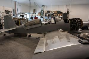 Tuesday afternoon we visited a Daytona Beach area RV–8 builder, who is installing a Rotec R3600 radial engine (150 hp, 3.6 litre, 9 cylinder engine) in his RV–8. I’ve got a soft spot for radial engines, as I flew the S–2 Tracker for 4 years, with two somewhat larger radial engines (Wright R–1820, 1525 hp, 29.9 litre, 9 cylinder engines - over 3.3 litres per cylinder!). BK is doing a beautiful job with his project. Terry was very jealous of the rear seat heat - he built custom sidewall panels and routed a hot air duct through the side wall to the rear seat and the passenger footwells (the stock ones get very cold).
Flying Again!
- Details
- Written by Kevin Horton
- Hits: 5161
Yesterday looked like the best chance to get the RV–8 flying again, so I took a day off work and headed to the hangar. It was very cold overnight, with a low temperature of –27°C, and it had been cold for the last several days, so I was expecting it to be miserably cold in the hangar. But, the hangar seemed to have retained some of the heat from the last warm spell we had, so it wasn’t too bad as I did a final inspection of the new exhaust system installation and reinstalled the cowling. Then while the engine was preheating I cleared the snow from in front of the hangar and had lunch.
After lunch the temperature was coming up nicely to –18°C and climbing, so I started the aircraft up, taxied to the gas pump and filled up. After refueling I climbed in, but flooded the engine when I attempted to restart it. I got it to fire once, but never managed to get it running before the battery quickly ran down. Drat!!
This latest Odyssey PC–680 battery doesn’t seem to have nearly the capacity of the previous two I had. I’m not the only one who has noticed, as many RV flyers are complaining that the recent Odyssey batteries aren’t nearly as good as the ones from a few years ago. Several owners have had good success desulfating the batteries using a desulfating procedure published by Odyssey, so I’ll look at refreshing the last battery I pulled out. I only replaced the last battery as Bob Nuckolls recommended annual replacement if you weren’t doing regular capacity checks. I’m wishing I had left it in now.
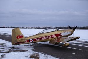 I pushed the aircraft back to the hangar, into the stiff wind, and over the patchy packed snow on the taxiway, uphill both ways. I was pretty bushed by the time I got it back in the hangar and on the battery charger. I left it on the battery charger for an hour, then it started right up. The wind was really stating to pick up by the time I got airborne, with the wind stock straight out (which suggests 25 kt or more), about 45 degrees to the left of the runway. I did a short flight, with two touch and goes then a full stop. The aircraft worked well, and it felt great to get it flying again for the first time in over a month. I’ll pull the cowling for an inspection before the next flight.
Four Pipe Exhaust System 99% Installed
- Details
- Written by Kevin Horton
- Hits: 5030
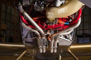 I spent several hours at the airport this weekend, and pretty much finished the installation of the four pipe exhaust system.
The large heat muff mounted over the pipes from cylinders #1 and #3 added a lot of time to the installation. First, I had to loosen the #1 pipe at the cylinder so I could rotate it a bit, to get the tail pipes at the correct spacing the match the two holes in the heat muff. Then, I found that the outer shell of the heat muff was perhaps a bit smaller than ideal, so it took quite a bit of clamping pressure to get everything lined up properly. Even with all that I was unable to get the two screws that secure the two halves of the shell together to thread into their nut plates. I ended up leaving those two screws out - the two clamps around the whole thing will hold everything in place.
 The hardware that connects the tail pipes together has mount points for supports that by design go pretty much straight up to the engine mount. But, the engine mount is fixed to the airframe, and the front end of the exhaust pipes move with the engine. It is far better to hang the tail pipes off the back of the oil sump, so all the supports move with the engine.
On the right side, with the large two pipe heat muff, the heat muff outlet interfered with a straight shot from the exhaust system mounting point to the oil sump. I puzzled over this for quite a while, and eventually ended up fabricating a horizontal bar that connected the two mounting points together, and then extended to the right. This allowed the support on the right side to pass outboard of the heat muff outlet.
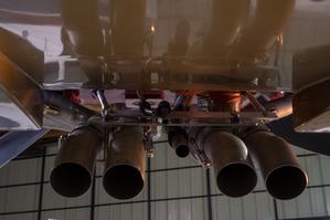 The second horizontal bar provided a convenient place to secure the fuel pump drain pipe and the sniffle valve drain. The breather tube was secured to the main horizontal bar which sits right on top of the two exhaust pipe supports.
I’ve got two things left to do:
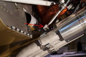
- The MS21919WDG12 “Adel” clamp that secures the breather tube is quite close to the tail pipe from #4 cylinder. These clamps come in a number of different variants with different materials. The “DG” ones in my collection have Chloroprene cushions, rated to 212°F (100°C). I’ve ordered a MS21919WCJ12 clamp with a Fluorosilicone cushion, rated to 450°F (232°C). I hoped it would be in stock at Aircraft Spruce in Toronto, in which case I would have it on Tuesday. But, it has to come up from one of their US warehouses, so it’ll be delayed. I’ll fly with the current clamp, and replace it as soon as the new one arrives.
- When I started to mount the second heat muff, on the #1 cylinder pipe, I discovered that the end plates were cracked. I’ll fly with just the big dual pipe muff for now, and order new end plates for the second muff from Robins Wings.
I left the cowling off in the hope that the new Adel clamp would arrive on Tuesday, and I would install it before flying. But, given that it will be delayed, I’ll try to get flying sometime this week, assuming we get the forecast good, but cold, weather.
Fuel Tank Reinstalled
- Details
- Written by Kevin Horton
- Hits: 3208
We had a forecast unseasonably warm day today, so I headed out to the airport to scrape the ice off the pavement in front of the hangar. Hopefully the airport will succeed in getting the ice off the runway, as we got hit by quite a bit of freezing rain over the last 10 days, and the runway was like a skating rink.
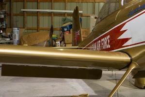 While I was there I finished installing the right fuel tank. This consisted of installing the 74 screws that go around the periphery of the tank, and reinstalling the wing root intersection fairing and the access panels on the bottom of the wing.
