Exhaust System Adjustment
- Details
- Written by Kevin Horton
- Hits: 3356
I also made some progress on the exhaust system today.
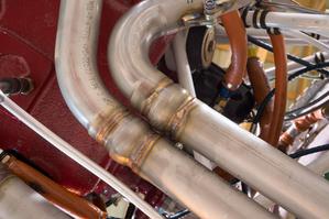 I had noted when I was last at the hangar that the ball joints on the pipes from cylinders 2 and 4 were touching. This was obviously not correct, and I feared that perhaps I would have to ship the exhaust system back to Vetterman exhaust for an adjustment.
I called Clint at Vetterman while I was at the hangar, and he gave me the info I needed to solve the problem. The holes on the flanges that bolt to the cylinders are slightly larger than the studs. Thus it is possible to rotate the pipes slightly before they are torqued in place. I loosened the nuts, replaced the lock washers, rotated the #4 pipe outboard, and the #2 pipe inboard, then retorqued the nuts. Now I have more than adequate clearance between the ball joints, and the #2 and #4 tail pipes are parallel, whereas before they were close together at the ball joints, then spread apart at the outlet.
I forgot my camera, so I didn’t get a shot after tweaking things today.
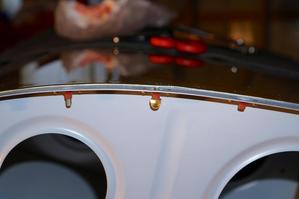
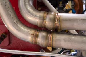 Update 11 Jan 2014 - Here is a shot showing the clearance at the ball joints after loosening the pipes at the cylinder, rotating, and torquing them.
Fuel Tank 75% Reinstalled
- Details
- Written by Kevin Horton
- Hits: 3184
My planned flight at work fell apart today, as the ramp at the hangar was a sheet of wet ice. It would be very unsafe to start engines, as the idle thrust would push the aircraft around with the wheels locked on the ice.
After I cancelled the flight, I took comp time for the rest of the day and headed to Smiths Falls. One of the other hangar tenants and I cleared the snow off the hangar tarmac, then I attacked reinstalling the right fuel tank.
The tank is secured to the wing by three different means:
- three bolts in each of seven Z angles that are riveted to the back bulkhead of the tank. You can see the Z angles in the picture on this page, from way back in 1998 when I was building the fuel tanks. The bolts are inserted from the aft side of the wing main spar, and thread into nut plates on the Z brackets. There are three access panels on the bottom of the wing to allow the bolts to be reached. Nine of the 21 bolts are easily accessed, but the other 12 require sticking an arm in an access hole, then reaching either inboard or outboard through lightening holes in the wing ribs to reach the bolt head. The aileron pushrod is in the middle of those lightening holes, so there is very little room for your arm to move. The holes for these 12 bolts cannot be seen, so you have to work by feel. If you drop a bolt, it skitters aft along the lower wing skin until it hits the rear spar, and then you have the fun of flailing around with a magnet on a stick to retrieve a bolt that you cannot see. Surprisingly, I managed to get all bolts inserted without drawing any blood, or inventing any new words. I only dropped one - that one came out on the third try with the magnet.
- There is a single 1/4" bolt that attaches the front end of the fuel tank to the fuselage.
- There are many dozen flat head screws around the periphery of the fuel tank skin, securing the edge of the skin to the wing skin.
I got items 1 and 2 done today, as well as reconnecting the fuel line, fuel vent line and fuel sender wires. All I have left to do is reinstall those many dozen screws, an easy but tedious task.
A very sharp cold front came through today, so the temperature has crashed again. I won’t be doing any more work in the hangar until it warms back up again - possibly on the weekend.
Fuel Tank Leak Sealed
- Details
- Written by Kevin Horton
- Hits: 3562
I dedicated three work sessions to the fuel tank leak repair over the last week.
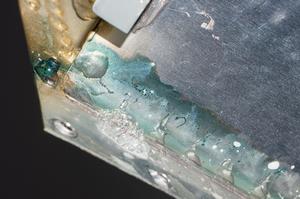 The first task was to apply a small amount of air pressure and use some soapy water to confirm the leak location on the outside of the tank. I pretty quickly found what I was looking for.
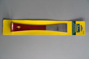 The next task was to remove the access cover on the inboard end of the tank. The access cover screws were easily removed, but the ProSeal sealant under the cover was very tenacious. I started with a sharp, thin putty knife. The flanges on the top, bottom and back only allowed me to use the putty knife from the front. I was able to slowly work it between the cover and the tank root rib, but the blade wasn’t long enough to reach all the way to the far side of the access cover. I went to Home Depot, and wandered the aisles until I found a 10" long scraper, which was the perfect tool for the job. It was long enough to reach all the way across the access cover, and I could use a hammer to tap on the other end to help things out.
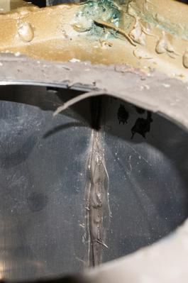 After removing the access cover, I put some soapy water inside the tank, in the same area as the leak on the outside, then used an air nozzle to blow compressed air at the leak area on the outside. I tried soapy water all along that seam, but couldn’t get it to blow any bubbles, so I never confirmed the leak location inside.
Looking at the sealant on the same seam where the leak is outside, it was obvious that some areas had poor adhesion, with small gaps between sealant and aluminum. I made a chisel out of a piece of Lexan, and used it to scrape the sealant off all along that seam. The sealant came loose quite easily - perhaps there had been poor surface preparation when I riveted the back bulkhead on the tank originally.
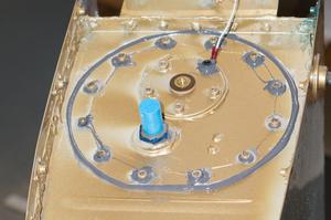 I cleaned the area of that seam with solvent, then roughed it up with a ScotchBrite pad, then cleaned it again. Then I applied FlameMaster CS 3204 sealant all along that seam (this stuff meets the same specification as the original ProSeal sealant I used when I assembled the tanks), and over the other seams in that bay. Then I put a bead of sealant under the access cover and secured it back in place.
Today, after four days of cure time, I did another leak check using air and soapy water. This time there were no bubbles at the original leak site. Hopefully this will have fixed it .
We’ve had a bit of a warm spell, which should continue tomorrow. I hope to get back to the airport late tomorrow to start putting the tank back on. I doubt I’ll get it finished, but it would be good to at least start.
Exhaust System Replacement
- Details
- Written by Kevin Horton
- Hits: 7860
Some time ago I decided to address the problem of recurring exhaust system cracks by install a new exhaust system. Larry Vetterman, founder of Vetterman Exhaust, suggested that a four pipe system would be more robust than my current four into two crossover system, as each pipe would be completely independent, with no connection to pipes from other cylinders. I was also considering a four-into-one system, but his performance tests of various configuration systems suggested that the four pipe system might yield a slight performance increase over the crossover system I have and the four-into-one system (more test results). I would have thought that a four-into-one system would be the fastest of all, but repeatable flight test data trumps theory every time. Decision made - a switch to a four pipe system was in order. I decided to get this done before next spring, to avoid any interruption of the good weather flying season.
I pulled the trigger in November, and asked Clint Busenitz (the current owner of Vetterman Exhaust) to make me a system. He was familiar with my recurring cracks, having repaired it twice (the third repair was done in the Ottawa area). He offered to build this new system with thicker than normal pipe at the cylinder flanges, as this is the area most likely to crack.
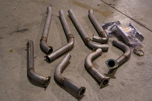 The new exhaust system arrived just before Christmas. Each cylinder pipe has a slip joint and a ball joint to allow the tail pipes location to be adjusted. The four pipe system also comes with a two pipe heat muff - this oval shaped thing fits over two adjacent pipes, and is reported to put out lots of heat. I also hope to resuse the heat muff I had installed on the #1 pipe, near the cylinder.
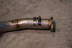 We had a short spell of warm weather over the last few days, so Saturday I removed the old exhaust system, and Sunday I started the installation of the new one.
The first big task is to drill the holes for the EGT probes. The probes should all be mounted the same distance from the cylinder, on a straight section, and no closer than 2“ to the cylinders. On my previous exhaust system those criteria drove me to put the probes 5” from the cylinders, which is farther than ideal. The EGT indications were always slow to respond to mixture changes, and I attributed that to them being a bit too far from the cylinders.
This new exhaust system has bends in slightly different locations, which allowed me to put the probes 2.5" from the cylinders. I wanted to be able to reuse the existing EGT probe wiring, which somewhat restricted the available clock angles on the pipes - some clock angles would require longer wires, and there wasn’t much slack available to do that. With the closer position to the cylinders, I also needed to be careful not to chose a clock angle that would have the protruding end of the EGT probe interfere with the lower spark plugs.
Stainless steel is a bit tricky to drill, and any round surface risks have the drill bit move around before it starts to cut. I fabricated a small drill guide from a piece of aluminum bar with a hole in it. I used two hose clamps to hold it in position for each hole. This worked a champ, after I acquired a suitable drill.
My hangar rechargeable drill with keyless chuck proved inadequate to the task. No matter how hard I tried, I couldn’t get the keyless chuck tight enough to keep the drill bit from spinning in the chuck once it started to cut into the stainless steel. I went to three different hardware stores in Smiths Falls today, looking for a cheap corded 3/8“ drill with a regular keyed chuck, like the one I had at home. No luck - lots of drills with keyless chucks. The only ones with keyed chucks were expensive ones aimed at professional contractors. I settled on a not so cheap 1/2” hammer drill, as I could use one of those. The hammer function can be turned off, and it did a perfect job on the exhaust pipes.
I was quite relieved when I had all four EGT probes mounted, and the hole locations proved satisfactory, with no interference between the probe ends and anything else.
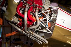
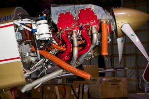
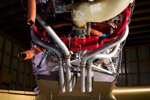 Here is a bottom view of the four pipe system.
I need to install the supports for the tail pipes and the heat muffs. I also must rework the support for the breather tube, etc that exit in the middle of all the pipes - they are just hanging there at the moment, as they were connect to the support for the tail pipes on the previous exhaust system.
A cold front went through overnight last night, and it will be much colder over the next few days. I’ll switch my efforts to the fuel tank leak repair, as that work is done in our basement.
Fuel Tank Screws Extracted
- Details
- Written by Kevin Horton
- Hits: 3533
I went out to the airport this morning to remove snow from in front of the hangar. You have to keep on top of the snow, or risk having it turn to ice from the heat of the sun bouncing off the hangar door.
While I was there I attacked the fuel tank screws that I had drilled the heads off when I was removing the tank. I had been worrying about this since the day I removed the tank, and had come up with several alternate fixes - two ways to hopefully remove the screws, and a couple of fall-back schemes to replace the nut plates if I couldn’t get the screws out. Replacing some of the nut plates would be difficult, as they were in very difficult to reach areas. I had hopes of using dental floss to pull the new nut plates in place so I could rivet them in place with blind rivets.
 Several of the screws were in an easy to access area, where the outboard edge of the fuel tank was secured to the upper wing skin. Here I used acorn nuts threaded on the protruding end of the screw to unscrew the screw a bit so I could grab the end with Vice Grips.
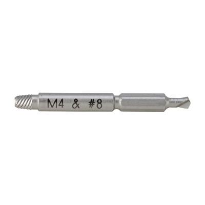 For the other screws, where I could not easily reach the end inside the wing, I used Alden Micro Grabit screw extractors. I found these guys at Lee Valley Tools - I knew if Lee Valley carried them that they would be good quality. They are a two ended tool, with a short left hand drill bit on one end, and a tapered left hand thread on the other end. The drill bit is left hand, so that it will tend to unscrew the screw remnant. After drilling the hole, you reverse the tool in the drill, put the tapered thread in the hole you just drilled, and slowly unscrew the fastener. The M4 size works well with #8 screws, as long as you drill the hole close to the centre of the screw. I was lucky in that the Phillips heads of the screws naturally centred the drill when I drilled the heads off, and the end of the drill bit left a depression in the centre of the screw shaft that helped guide my drilling efforts today.
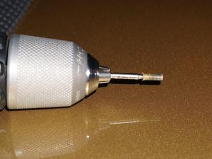 I have tried many different kinds of screw extractors in the past when I had broken off bolts, but the Micro Grabits are the best of the bunch. I had bought two of them, as I have invariably broken off a screw extractor in the past. But today, these things worked like magic, and I had all the offending screw ends removed in about 30 minutes. I’ll sleep a lot better tonight knowing that this part of the fuel tank issue has been resolved.
Fuel Tank Removed
- Details
- Written by Kevin Horton
- Hits: 4277
Thursday I spent several hours at the hangar, removing the right fuel tank. I had noted a significant amount of blue fuel dye stain on the lower wing surface, running aft from the inboard end of the fuel tank. This had first been noted some time ago, but it stopped, so I ignored the issue, hoping that the problem had definitively fixed itself. But, it started up again recently, much worse than before. So, it was time to do something about it. I’d rather have the aircraft out of service in the winter than the summer - I decided that now is the time to do this repair.
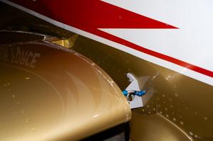
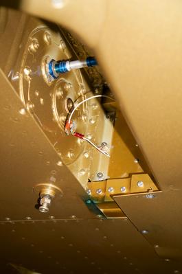 This view is from below the aircraft, looking at the inboard end of the right fuel tank. You can see the blue stain from the fuel leak.
 It took about three hours to get the tank off. Step one was removing the wing root intersection fairing, and disconnecting fuel line, fuel vent line and fuel sender wire.
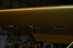 Step two was removing the bolts attaching the fuel tanks to the wing spar. The bolts are reached via three access panels on the bottom of the wing. It was a load of fun reaching some of those bolts, but that’ll be nothing as compared to what it will take to get them back in. I suspect I may have to disconnect the aileron pushrod to give more room to get my arm in.
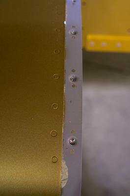 Step three was to remove all the screws around the periphery of the fuel tank. This proved to be a problem, as many of the Phillips screw heads on the upper wing surface were filled with clear coat from when the aircraft was painted. Try as I might, I could not get the screwdriver bit in deep enough to turn some of the screws, nor could I dig the clear coat out of the screw heads . I ended up drilling the heads off numerous screws, so now I’ll have the fun of extracting the remains of the screws from the nut plates, or removing and replacing the nut plates with new ones.
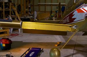 Here we are, after the fuel tank was removed. You can see blue fuel stain on the front of the wing spar, near the fuselage.
I got a lot of good advice on locating the source of the leak, and materials and techniques for completing the repair from other RV builders on the Van’s Airforce forums. I’ve got some more stuff on order, so it’ll be a few days before I can start the meat of the repair. I’ll use whatever warm days we might have to go to the hangar to attack the drilled off screws.
