Wings in jig
- Details
- Written by Kevin Horton
- Hits: 4141
I got back from two weeks in Wichita on 7 Oct 98. I finished riveting the wing ribs to the spars on 8 and 9 Oct. On 10 Oct I started working on the wing jigs.
The wing jig consists of two vertical posts, with horizontal arms attached. The wing spars are clamped to the horizontal arms, and the whole thing is carefully aligned with levels and plumb bobs.
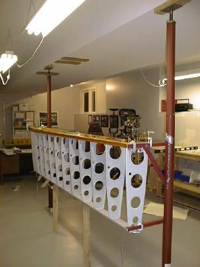 Originally I planned on reusing the jig I built for the tail surfaces (picture). Most people simply remove the cross member from the tail jig, and voila, you've got a wing jig. Well, fate intervened, and one of the vertical posts developed an impressive warp after I finished with the tail jig. I had already decided I wanted two wing jigs, so I could work on both wings in parallel, so I would have had to move the tail jig anyway.
I decided to use steel posts this time - jack posts usually seen in basements. Here you see the left wing in the jig part way through the leveling process. The two small posts under the rear spar are there because the spars sag under their own weight. The small posts hold the spars straight while the skins are being drilled on. Once the skins are on, the whole structure will become stiff.
I will put the jig for the other wing parallel to this one, to the right. I am waiting to set it up until I can confirm that the dimensions and wing support provisions I did for the first jig work OK.
Left Wing Skeleton
- Details
- Written by Kevin Horton
- Hits: 3284
Here is the left wing skeleton, with the outboard end closest to the camera.
The area at the inboard end where there are no nose ribs is where the fuel tank will be. The fuel tank forms the inboard half of the wing leading edge.
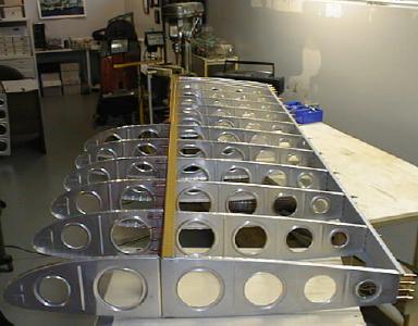 I've got to deburr all the holes I drilled, drill some holes in the ribs to run a conduit and pitot line through, prime the ribs, and then I can rivet the skeleton together and put it in the wing jig.
Wing Skeleton
- Details
- Written by Kevin Horton
- Hits: 3052
Here I am drilling the main wing ribs to the main spar.
The spar comes with pilot holes where the ribs mount.
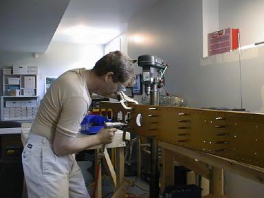 I drew lines down the centre of the flanges at the front and back of the ribs. Then I clamped the ribs in place, making sure that I could see the line on the rib through the holes in the spar. Then I drilled the full size holes through the spar and rib, putting clecos in as I went.Drilling wing ribs to main spar
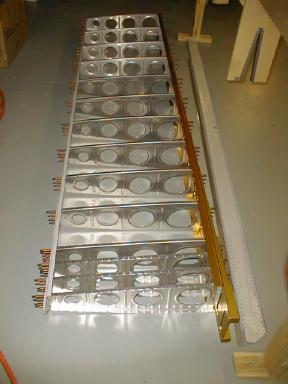 Here is the right wing with all the main ribs clecoed on.
It felt pretty good to finally have a large part taking shape before my eyes.
Main ribs fluted
- Details
- Written by Kevin Horton
- Hits: 2914
I just finished deburring and fluting the main ribs. It took about 35 minutes per rib, and is pretty tedious work. I need a break from deburring and fluting, so I will drill and cleco the main ribs to the spars next, then attack the nose ribs.
Wing Ribs
- Details
- Written by Kevin Horton
- Hits: 3163
The wing ribs are in two pieces, the nose rib and the main rib.
The nose rib goes ahead of the main spar and forms the curved front of the airfoil.
 The main rib goes between the main and rear spars.
The sharp trailing edge of the airfoil is formed by the flaps and ailerons, which attach to the rear spar.
Each wing has 14 main ribs and 15 nose ribs.
 The wing ribs are made from one piece of metal, with the edges bent over to make flanges.
The ribs are delivered bowed, because the outline is curved, and the flange causes a bow when it is bent over. You can see that the bow in the rib causes the ends to lift up off of the work bench.
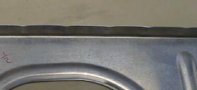 The bow in the ribs must be removed. This is done by forming flutes in the flanges.
The flutes basically shorten the flanges slightly, which removes the bow in the rib.
The flutes must be carefully placed so that no rivets will end up going in the area where a flute is.
Wing Rear Spars
- Details
- Written by Kevin Horton
- Hits: 3422
Here are the completed wing rear spars. I just finished riveting them this morning before catching a plane to Wichita.
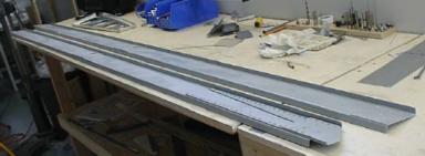
 Here is a close up of the left rear spar inboard end. There are reinforcing plates to transfer the loads from where it bolts to the fuselage (right end) to the rest of the spar.
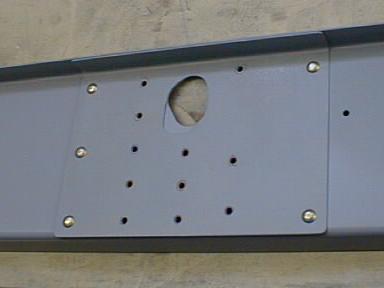 Here is a close up mid span portion of the left rear spar.
You can see the reinforcing plate where the inboard aileron hinge mounts.
There is a similar reinforcing plate at the outboard end where the other aileron hinge mounts.
The empty rivet holes will be used to attach the aileron hinge bracket and a wing rib.
The large hole is there to allow the aileron pushrod to go to the aileron.
