Heated pitot tube mount
- Details
- Written by Kevin Horton
- Hits: 8596
Van's standard pitot tube is simply a piece of aluminum tubing which comes straight down from the main wing spar and is bent to point forward. It's effective, simple and cheap, but is not heated. I plan on flying IFR, so I need a heated pitot tube to cover the possibility of getting caught in icing conditions.
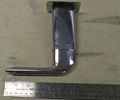 I bought a standard AN5812 heated pitot tube from Aircraft Spruce, and a mounting kit from GretzAero. The mounting kit is very well done. The bracket is a piece of aircraft streamline tubing welded to a plate, and the whole thing is nicely chromed. A backing plate to rivet inside the wing and all the needed hardware are included. The instructions are very clear.
The pitot tube was a pretty tight fit into the mount. I had to put a bit of never-seize on it to allow it to slide in without scratching up the chrome on the pitot tube. One of the bolt holes on the mount had to be enlarged slightly with a needle file to allow the mounting screws to fit properly.
I will be using the Van's standard static source on the rear fuselage because it appears to work well, and should not collect ice. I will have an alternate static source in the cockpit just in case. Some builders use an AN5814 pitot tube with static source, but I would expect to get large static source position errors that way. A static source needs to be in an area with the same pressure as the free stream air, but a wing is specifically designed to have high pressure underneath, so it takes a lot of trial and error to find a decent location for a wing mounted static source.
Read on for more.
Riveting the fuel tanks
- Details
- Written by Kevin Horton
- Hits: 4173
Well, it sure took forever to finally start riveting the fuel tanks parts together.
First, I went back into travel mode for several weeks. I spent about two weeks in Tel Aviv, Israel flying the IAI Galaxy business jet. Nice aircraft, fascinating country, and great people. While I was there I visited RV-8A builder Ariel Arielly.
I went straight from Israel to Scotland to do some natural icing testing on the Global Express for about 10 days. Lots of fun, but it does feel different to be looking for ice instead of trying to avoid it. We found huge amounts of ice north of Iceland.
 After I got back home, I was spooked by the thought of working with Proseal, so I got motivated to do all kinds of other little jobs that I had been putting off. That stuff needed doing anyway, so the time was not wasted.
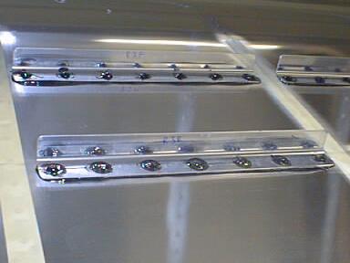
Finally, this weekend I bit the bullet, mixed up some Proseal and started riveting the stiffeners to the bottom of the right tank skin. Other than not mixing up enough Proseal and running out near the end, it went really well.
Here you can see a few stiffeners. The black stuff around the edges and on top of the rivets is the Proseal. It comes in two parts and you mix it together. It sets up into a rubbery sort of stuff that stands up well to fuel. It is needed to make sure that no fuel leaks around the rivets, which is why the rivet heads are covered with it. It is also applied in between the tank skin and the stiffeners to make sure that no fuel gets between the two and out the rivet hole.
Firewall
- Details
- Written by Kevin Horton
- Hits: 3708
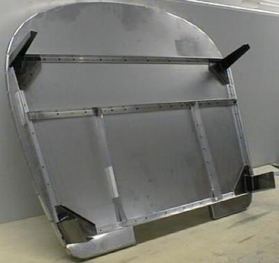
Here is the firewall after drilling and clecoing it together. I've got to prime the parts (except the stainless), and then rivet it together.
 The fuselage kit arrived while I was away on the road. It wasn't supposed to get shipped until after I got back, but there was a screwup and it got sent early. Fortunately my boss volunteered to pick it up at the shipping deport, and some coworkers helped him get it in the garage. Thanks guys!
First I had to unpack the crates and check everything against the packing list to make sure it all arrived. It turned out that I had the right number of parts, but one was damaged, and another one was meant for an RV-8A (version with a training wheel on the front) instead of the RV-8 that I am building (third wheel on the back, preferred by "real men" :-) Vans is sending the replacement parts.
Read on for more.
Inverted fuel mods
- Details
- Written by Kevin Horton
- Hits: 6259
Van details a series of modifications that can be done to allow a fuel tank to feed fuel even if the aircraft is in inverted flight. I decided to do these mods to the left tank.
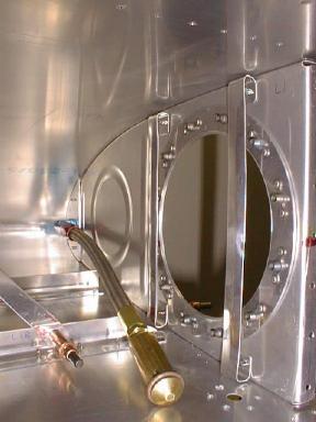 Here you see inside the inboard end of the left tank, looking forward. The back wall of the tank has been removed.
You can see the large hole where the inspection cover is in the inboard rib. The bolts that fasten the inspection cover on screw into the plate nuts that you see riveted to the reinforcing ring.
You can also see the flop tube, a flexible tube with a weighted end through which the fuel feeds. No matter which way the aircraft is pointed, the fuel and the flop tube end up in the same corner of the tank (except if you are going straight down - it is not flexible enough to go to the front of the tank).
The two vertical strips by the inspection cover are there to keep the flop tube from getting hung up on the anchor nuts.
The tank ribs have two large holes in them to allow the fuel to flow from bay to bay. If you do the inverted fuel mod, you have to deal with these holes. In upright flight, the fuel will stay in the inboard bay (where the fuel pick up is) due to the dihedral of the wings. But, in inverted flight, the fuel will want to go to the outboard end of the tank, and the fuel pick up will be sucking air.
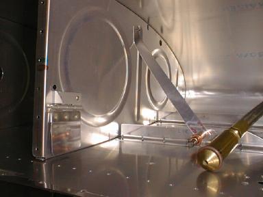 The rib which forms the outboard end of the first bay in the tank is modified to address this problem. One of the holes is left out of this rib. The other hole is covered with a little flapper valve made from a piece of aluminum and a piece of piano hinge. The valve will swing out of the way to allow fuel into the inboard bay, but it will close off the hole to slow the exit of fuel from the bay in inverted flight. The fuel will leak through the flapper valve, and also through the smaller holes, so you can't stay in inverted flight too long.
You can also see a strip of aluminum that will be riveted between the rib and the stiffener on the bottom of the tank. This strip keeps the flop tube from getting into the corner between the stiffener and the rib and getting hung up.
The fuel sender normally goes in the inboard bay, but it must be moved to the second bay, so the flop tube doesn't get hung up on it. The sender must be mounted on the rear baffle, whereas it is mounted on the inboard rib in the basic installation. This means that the bending diagram that Van supplies for the fuel sender wire doesn't work. The attached tracing shows how I bent my fuel sender wire.
Right tank on the bench
- Details
- Written by Kevin Horton
- Hits: 5731
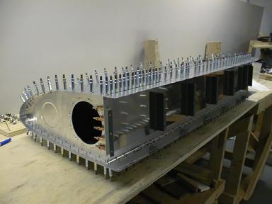
Here is the right fuel tank all clecoed together, after I pulled it off the wing.
You can see the seven Z-brackets that hold it to the spar and the hole for the access cover in the root rib.
 Now I will start working on the left tank, and get it caught up to the right.
We are heading away for 10 days over the holidays, so things will go on hold again.
Fuel tank skin clecoed
- Details
- Written by Kevin Horton
- Hits: 3652
Its been a busy few weeks. At least I did a bunch of good flying - several good test flights on the Canadair RJ (it really seems like a truck after the Global Express), Canadair Challenger and Global Express. And to top it all off, I got a ride in a beautiful RV-4. It doesn't have quite the performance of the other stuff I was flying, but it eats them alive in fun factor :-)
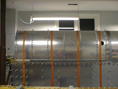 Here you see the right fuel tank with the skin strapped down and drilled and clecoed to the top side of the ribs.
You can see the hole where the fuel filler cap will go, to the right of the rightmost strap.
Things have really slowed down due to all the normal Christmas stuff. It is amazing how much time it takes for buy all the presents, do Christmas cards, go to Christmas parties, etc. I'll be lucky to finish drilling the right tank and get the skin trimmed before we head away for Christmas.
