Trim wiring, backlighting, etc
- Details
- Written by Kevin Horton
- Hits: 3412
I spent a lot of time in the aft fuselage the week before last, running and securing the wires for the electric trim. It sure is a pain to get all the way back in there. You need both hands above your head to do some of the work, but it is so tight that your elbows hit the bulkhead and won't let you put your arms up there. So, you have to get your arms above your head before moving into the last bay.
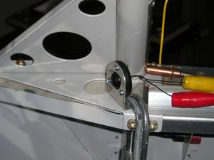
I mounted the trim servo in the elevator and puzzled out how to secure the wires as they went from the elevator, into the horizontal stab and then to the aft fuselage. I hooked up the front end of the trim wire and did a complete functional test - front seat trim switch, rear seat trim switch, trim disable switch on stick, rear seat trim disable switch on side console. It all worked.
I had hoped to get the roll trim hooked up that week too, but I ran out of butt splices to hook up the wires. I was going to finish the mechanical installation, but I couldn't find the long piece of 5/16 aluminum tube used to go between the servo and stick. I found two pieces half as long as I needed, but the long guy was missing. I finally remembered what happened - I had screwed up the flap pushrods, and had to use that long piece of tube to make them from. I had planned on replacing it and then forgot about it. Coincidentally I had purchased a long piece of the same tubing a few weeks ago to make some spacers from. I had just made a few spacers earlier that day - I measured how much remained of the tubing and it was a half-inch too short. If I had only noticed that I had those two shorter pieces of tubing I could have used them for the spacers instead. Oh well. One more thing to order from Van's.
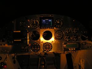
I've spent a lot of time over the last two weeks messing around with dimmers for the GNS-430 GPS, GTX-327 transponder, Microair com, Garmin CDI, Van's engine instruments, etc. There are several different types of light technologies involved, and each one has its own curve of light intensity vs input voltage. And the GNS-430 and GTX-327 each has several variables that you can set to customize the intensity vs input voltage. I don't want a separate dimmer knob for each unit, so I need to figure out how to set them up to allow me to use as few dimmer knobs as possible, yet have the lighting on all units remain in balance no matter what intensity I want. I'll have a lot more empathy for the poor designer next time I do a night lighting evaluation of an avionics mod, and note a problem with the lighting balance.
I think I am zeroing in on a solution. The GNS-430 and GTX-327 will get their own separate rheostat, as the solid state dimmer I have for the LED flood lights won't go to a low enough voltage to work with the logic built into those units. They are designed to stop following the dimmer and set the intensity based on a photocell for daylight operations. The Microair com backlighting will work nicely if I feed it from the solid state dimmer for the LEDs. And the CDI, engine instruments, etc will have to be on their own solid state dimmer, as they are all incandescent lights they should have roughly the same curve of intensity vs voltage (I hope - I haven't proven this yet)
I had originally planned to just have the LED flood lights, so many of my instruments do not have internal lighting. But some of them do, and I've decided to use the internal lighting on the CDI and engine instruments. The EFIS is lit, and it has attitude, heading, airspeed and altitude. The CDI and engine instruments will be internally lit. The round dial airspeed and altimeter are of lower importance, so I can accept a bit lower light level from the LED floods.
I also pulled out the avionics rack for a while so I could reroute part of the wiring harness that was too close to some structure.
LED Flood Lights, Avionics Rack, GPS fit, etc
- Details
- Written by Kevin Horton
- Hits: 3737
I primed the avionics rack support pieces Friday night and went to rivet the nutplates on Saturday, only to discover that I didn't have enough of them. Oh well, I guess its time for yet another order of odds and ends, as I have a half-page list of little items.
I made a very welcome discovery with the Garmin GNS-430 today. It has always been quite finicky to get it to fully slip into the rack. Today I finally took the time to properly investigate the reason. Once I looked carefully at the back of the GNS-430, I could see that one of the connectors showed evidence of hitting on the edge of the backshell, rather than slipping properly in place. Once I knew what was going on, I tried removing the transponder from its tray, and sticking a finger up from below the panel to push up on the end of the GNS-430 as I slipped in place. This allowed that connector to mate properly the first time without all the jiggling that it used to need. It sometimes used to take five minutes of messing around to get the GNS to properly mate with its connectors.
I finished the wiring for the cockpit flood lights on Saturday and today I removed the canopy bow so I could install the plate nuts that the flood light supports bolt into. I had thought about changing my mount to be similar to the one that a viewer has on his RV-6, but I determined that moving the floods further forward and outboard would provide even worse illumination than my current marginal setup.
Today I attached the routing and connections of the static line. I had previously run it from the aft fuselage static ports to the instrument panel area, but now I need to run it to each instrument that requires it. I had a concept of how I would route it, but today I decided that Plan A wasn't going to work, as there was a dearth of places to secure the polyurethane tube to keep it from getting chafed. I came up with Plan B and secured the tube in several places to get it up behind the airspeed indicator. I had previously order a bunch of fittings to go with Plan A, but I need a slightly different mix of fittings for Plan B. So I'll stop here until the other ones arrive.
This evening I spent a bunch of time poring through catalogs so I could order the stuff I need. And of course no one vendor carried everything I needed, so I had to put in two orders.
I'm not sure what I'll work on this week. Perhaps I'll try to finish off the pitch and roll trim wiring.
Avionics rack support and CDI
- Details
- Written by Kevin Horton
- Hits: 4639
I started fabricating the avionics tray support on Monday, but I didn't like the way the first concept fit together, so I scraped it and went onto Plan B. The first two-thirds of Plan B was fabricated on Tuesday.
Wednesday I was really, really tired, so I knew I shouldn't work on anything critical, expensive, or that I had already invested a lot of time in. But I figured I could safely work on the avionics rack support, if I was careful. Well, I was wrong. I made an error doing some mental math and cut two pieces too short. Of course I didn't note the error until I had already completely trimmed, drilled and polished the pieces. Lesson learned (again) - don't work on the project when I am too tired.
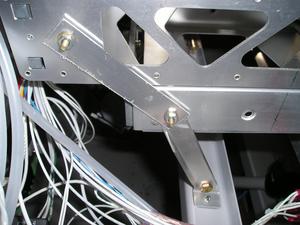
 I took the afternoon off today and finished the avionics rack supports. I'll rivet the nutplates on tomorrow after the paint dries and then install it. This photo shows the avionics rack support before the top pieces were finished. The pieces supporting the lower tray were made from some 3/4 x 0.063 angle, with one leg mostly trimmed off. I thought of just using some 0.063 sheet, but I wanted something stiffer laterally to be sure they didn't have a buckling mode failure when I pulled a bunch of g. I probably could have tried to calculate how thick the sheet would have to be to ensure it didn't buckle, but it was easier to trim down a piece of angle. The upper pieces will only be loaded in tension, so they are 0.040 sheet.
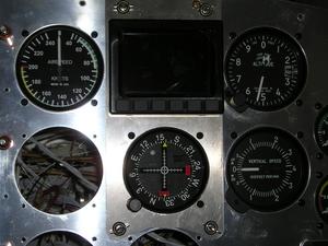
 Today I also filed a cutout for the CDI course knob so I could move it up one slot to put it right below the EFIS and started the wiring for the cockpit flood lights.
The wiring sure looks a mess in these photos. I have a lot of work to do to finish tidying it up into bundles.
Instrument Flood Lights, etc
- Details
- Written by Kevin Horton
- Hits: 3351
I got back from Wichita Thursday night. I think that will be my last trip there for at least two months. Yesterday I spent a good little while sitting in the cockpit in the dark with two LED flood lights powered up. I tried clamping them down in various locations, looking for the best compromise. I finally decided that the best location was near the canopy bow, just ahead of the end of the canopy rail. I had tried a location further back, hoping to get a more direct line at the instrument panel to get rid of some of the shadows. But that ended up putting the left light in the perfect location to reflect off that big GNS-430 screen and right into my eyes. Not good at all.

Once I knew where the flood lights were going to be mounted, I finished fabricating the mounting brackets and drilled the holes to bolt them in place and drilled holes to run the wires.
Today I mounted the B&C dimmer module, and was getting ready to start running the wires when I got side-tracked. My eyes fell on the pieces of angle that the avionics trays bolt to. I remembered that two of the bolts didn't yet have nut plates, as I had run out of the type I needed. Those nut plates arrived months ago, but I had never riveted them in place. This job would only get more difficult as more stuff was installed, so I decided to remove enough stuff so I could install them today.
Next I was going to run the wires for the LED flood light, but I realized that the ones coming from the dimmer really needed something to attach them to so they wouldn't flop around. The rear support for the avionics trays would be the perfect place to attach those wires to, but I haven't fabricated it yet. I spent a while with pieces of scrap aluminum and puzzled out a simple, strong and relatively light solution, which I'll fabricate this week.
Flight Test Data - very small steps
- Details
- Written by Kevin Horton
- Hits: 3974
I spent quite a bit of time learning Perl, a computer programming language. I think I will use Perl to write programs to record the data from the Dynon EFIS, Grand Rapids EIS and Garmin GNS-430. Dynon and Grand Rapids provide instructions or programs to record data from their boxes, but there is no way to time-sync the data from different boxes. I.e. you can't figure out which data records from one box happened at the same time as a given data record from another box. And Garmin doesn't provide any software or instructions at all, but I do know that the box will output serial data, so I just need to figure out how to record it. I think I will write my own software to record and time-stamp the data from all three boxes.
It has been many, many years since I had to learn a programming language, so it was a challenge to dig into Perl. But I like a challenge. Once I had the basics figured out I wrote a couple of Perl scripts to help create Canadian databases for the fplan Unix flight planning program, which I managed to get running on OS X.
It looks like Perl will work to record the data, once I figure out how to get the three data streams into a laptop computer. There are several devices that should work, but I've got to do some research and buy one.
Goose Neck Light
- Details
- Written by Kevin Horton
- Hits: 2779
I finished wiring the goose neck light yesterday, but it wasn't working properly. It would go out if I flexed the goose neck outboard - not good. I spent quite a while today trying to figure out what was going on. I determined that the problem wasn't in the removable goose neck part. Rather one of the pins was making an intermittent contact where the goose neck plugged into the socket. I think I may have got the receptacle too hot when I soldered the power wire to it. I ended up bending one of the pins slightly to force it to press sideways against the side of its receptacle. Hopefully this will do the job, as it would be a pain in the your know what to solder a new socket in place.
 The lamp does quite a good job of lighting up the panel. It will be my emergency instrument panel light, and I suspect I will use it to fill in the shadows that the LED flood lights leave. I think I will be able to flex the goose neck to sit ahead of my chest shining forward when I night fly.
The B&C dimmer assembly doesn't kill the light completely when it is turned to the minimum position. The intent is to leave a small amount of current flowing in the bulb to keep it warm and thus extend its life. I knew the dimmer worked like that, but the lowest intensify is higher than I expected. I won't know until I do a night flight whether that will be a problem or not. It won't be a problem if I keep the lamp facing at the instrument panel, but it might be a distraction if the lamp is facing in some other direction.
I'm heading on the road tomorrow for a week or so, but I think that will the last trip I do for quite a while. I need to get back into a regular building routine and make some good progress.
Another big order of stuff arrived from Van's a few days ago, so I have lots of things I can work on when I get back.
