Alternate air door pictures
- Details
- Written by Kevin Horton
- Hits: 5919
I took some pictures of the alternate air door installation, but in case other RV-8 or RV-7 builders are wondering what it looks like. These pictures are applicable to RV-7 or RV-8s with Van's horizontal induction system (i.e. 200 hp IO-360A series engines, or the oddball 180 hp IO-360-M1B with fuel injection servo on the front end of the oil sump).
So far, I am quite impressed with the basic concept. It looks like it should work quite well. The only question in my mind is whether it will be possible to close the door while the engine is running, or whether the cowling will need to be pulled off to push the door closed. But it should open reliably, as it is pulled open by the push-pull cable.
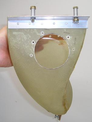 The first picture shows the hole that must be cut in the left side of the induction snorkel.
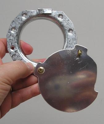 This shot shows the flange that will be riveted to the induction snorkel, and the pivoting door in the open position. A push-pull cable will actuate the door.
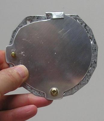 Here is the door in the closed position. The bent over part of the flange at the top holds the door tight against the flange.
Slow Progress
- Details
- Written by Kevin Horton
- Hits: 3922
I've done quite a few short trips in the last few weeks, and also done a few minor projects around the house. Progress on the RV-8 project has been slow.
I've finished the annunciator light installation, and done a fair bit of experimenting with programs to record flight test data. I'll write up all the details on recording flight test data once I get everything completely sorted out.
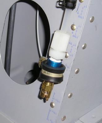 I plumbed the pitot and static lines behind the instrument panel, including an alternate static port, and did a leak check. The alternate static port is just a Curtis CCA-1550 fuel drain valve. It is spring loaded closed, but can be turned and locked into the open position. The vertical piece of static line that it is on also acts as a moisture trap for part of the static system. Moisture can be drained by opening the valve. I'll be installing another vertical line and plug in the aft fuselage, at the point that is lowest when the aircraft is sitting on the ground.
I had been agonizing over how to design an alternate air door for the induction air. But Van eventually designed alternate air door kits for all the RV models, following an accident and an incident with RVs that were attributed to snow blocking the air filter. His design is certainly a lot simpler and lighter than the idea I had in mind. I started installation of alternate air door this week, but had to stop as Van sent the wrong rivets. I've order the correct rivets, and I'll pick up this part of the project when they arrive.
Today I drilled the holes for the jacks for the GNS-430 data line and for the music input into the PMA-4000 audio panel. I wired up a line to go from Terry's iPod to the music jack, and did a functional test. It worked great! The auto panel automatically mutes the music if anything is heard on the radio, or if we talk on the intercom. The muting for radio traffic is only for the front seat though, which is probably OK, as I suspect Terry won't be too interested in ATC stuff.
I've also spent too many hours puzzling over how to control the sliding door I built to control the airflow into the oil cooler. I had a concept, and obtained a control cable. But I discovered that the cable didn't have enough travel. So I then pondered making a bellcrank with different length arms to multiply the travel. I spent quite a bit of time figuring out how long the bellcrank arms needed to be, where to pivot it, how to support the pivot, whether it would interfere with anything else, etc. It was turning into quite a nightmare. Then another builder suggested I just use a Bowden cable without a knob on the end, as then the travel could be whatever I wanted. Of course I would still need to come up with something on the cockpit end instead of a knob. I think I have devised a lever arrangement that will work. I'll build up a prototype sometime to try it out.
Flight Test Data, ASI Cal, etc
- Details
- Written by Kevin Horton
- Hits: 6145
I've been working on a bunch of different stuff over the last two weeks:
Flight Test Data - I ordered a Keyspan 4-port USB to serial adapter, and it arrived about 10 days ago. It allows me to get the data from the Dynon EFIS, Grand Rapids Engine Monitor and the Garmin GPS into a laptop. I started messing around writing a Perl script to record EFIS data. If I only wanted to get data from the EFIS, I could just record it with a terminal program, but I want to get data from two or three different things, and I want to be able to time-sync the different data streams. In other words, if I see something of interest in one data stream, I want to be able to identify when it occurred, so I can see what the data from the other boxes shows at that time. I have a tendency to become focused on some things, so I ended up spending much of the Easter long weekend pounding away at my computer keyboard, writing an debugging the Perl script. I finally had an Eureka moment and got it working. I'll attack the scripts for the engine monitor and GPS later.
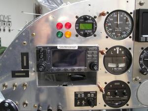 Annunciator Lights - I finally drilled the holes for the four round LED annunciator lights. I didn't have a lot of extra room to play with, and I wanted to be sure to get them perfectly lined up. I did a lot of head scratching, and finally realized that I should make a template. That way I could guarantee that the holes ended up where I wanted. The lights mount from the cockpit side of the instrument panel, so I needed a way to disconnect them - I've soldered wires on them that go to knife splices. I haven't yet run the wires from the aircraft to the lights.
Airspeed Indicator Calibration - Airspeed indicators always have some error, and a knowledge of that error is essential if you want to be able to sort out the static system position error using a speed-course flight test technique. A lot of people don't bother figuring out what the static system position error is, but I plan to fly IFR, and the static system position error affects the accuracy of the altimeter, so I will do the required testing.
The first step is to calibrate the airspeed indicator. I made a water manometer from a piece of 3/8" clear vinyl tubing, as described on the EAA Chapter 1000 website.
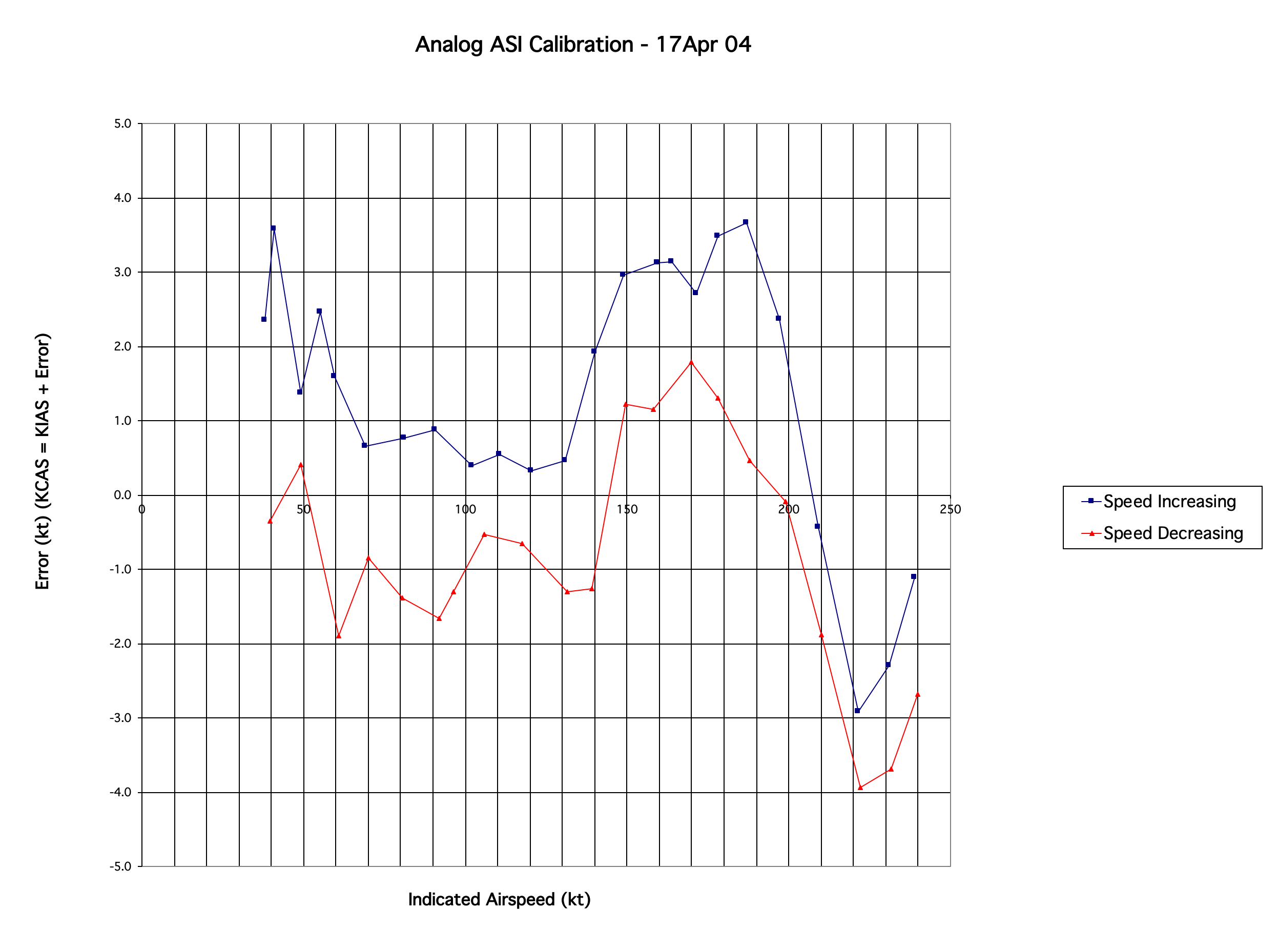 I gathered data from about 40 kt to 240 kt with the speed increasing between each data point, and then reversed the process with the speed decreasing between each data point. You can see how the friction in the analog airspeed indicator produced some hysteresis. I'll assume that the vibration from the engine will remove the hysteresis in flight, so I'll use the average of the two lines when I use this calibration data.
The ASI reads a bit low at low speed, is quite accurate from about 70 kt to 130 kt, reads up to 3 kt low from about 150 kt to 200 kt, and reads high above 200 kt.
 I was somewhat surprised to see some apparent hysteresis in the EFIS airspeed as well. The EFIS airspeed was more accurate than the analog ASI, but it has some small errors. I also checked the data that was transmitted by the EFIS, and it seemed to compare well to the values displayed on the EFIS, although there was a bit of noise in the data, and I should have recorded a longer burst of data at each point. I'll probably repeat this part of the calibration later.
G-Meter Mount
- Details
- Written by Kevin Horton
- Hits: 3261
I had visions of being close to being able to rivet the upper forward skin on. But, I sat down and took a close look at the forward fuselage and realized that there are many things left to do that will be easier if that skin is not on. So, I'll hold off riveting that skin until I have finished the following:
- alternate air door control
- heater box controls (2)
- oil cooler door control
- cigar lighter (power source for hand held GPS, iPod, etc)
- annunciator lights
- trim front right corner of alt encoder shelf
- secure all wiring bundles
- run coax for Com 2 down to wing root area
- run coax for NAV down to wing root area
- finish wiring for eng inst & compass lights
- GNS 430 serial data port for flight test data
- G-meter mount
This week I messed around with the compass lighting. There is some sort of intermittent connection at the light fixture, so it only works if I fiddle with it. I could't get it sorted out, so I decided I can live without a light in the compass. The flood lights provide some light over there, and I've got a slaved compass heading in the EFIS, so I really won't need to check the magnetic compass too often.
I also spent a fair bit of spare time working on the Pilot's Operating Handbook for the aircraft. I started with a nice one that an RV-8A builder had done, but there is quite a bit of editting to do to make it match my aircraft and my way of thinking.
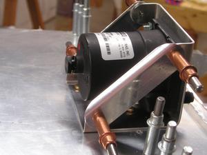 I looked at the list of stuff to do before riveting that skin, and decided to make a g-meter mount. It took a bit of head scratching to come up with a design, and then a fair bit of time to get it actually made. But I turned out great. It felt good to be bashing metal again. That is the part of the project that I enjoy the most. I need to decide what colour to paint it, then rivet the two diagonal arms on. It sits right in the middle of glareshield, with the centre of gravity of the g-meter located right on top of the instrument panel, so it won't want to lean either fore or aft when I pull g.
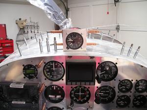 I sit high enough that the g-meter won't block any of the forward view. The spinner will still be visible above the g-meter.
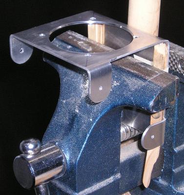 The top of the glareshield is a bit curved, so I had to bend the bottom of the mount so it would sit flat.
Annunciator panel, headset jacks, instrument light dimmer
- Details
- Written by Kevin Horton
- Hits: 3121
It was very sunny Monday, so I took a few hours off work and came home to try out the LED light bars. I modified the bread board to run off a battery and took it outside. I started with the nominal design current of 0.020 amp. It was not possible to tell whether the light bar was illuminated unless I put it in the shade, and even then it was not very bright. I tested several more times at higher and higher current, eventually getting up to 0.060 amp, or three times the design current. I considered it marginally acceptable at 0.060 amp, but I am concerned about the life. It was still not that easy to see it, unless it was in the shade.
So, time to rethink my plan. I think I will use the red round LED that came with the EIS-4000. I bought amber and green versions from a major electronics supplier too. There are a bit brighter, but I didn't want to use them as I don't like the look. But, I don't want to waste a lot of time on a science experiment, so I think I'll go with them to get flying quicker. I will almost certainly redo my instrument panel after I get flying, as I won't need the removable centre portion of the panel if the Dynon EFIS works out. I'll change over to some better looking annunciator lights at that time.
I finally finished running the wires for the rear seat headset jacks and soldered them to the jacks. Not a fun task, and not a pretty solder job. But they work.
The weekend I installed yet another B&C dimmer module for the incandescent lights (CDI, engine instruments and compass). I was quite disappointed to find that it didn't work after I finished installing it. I checked all the wiring with a multi-meter, and found no faults. I figured there had to be a problem with the dimmer module itself. Maybe a bent pin. So I removed it and gave it a careful looking over. The pins looked OK, so I started inspecting the printed circuit board. I eventually noted that it didn't seem to match the schematic in the installation instructions.
Then I finally realized what the problem was. I had used the wiring diagram from the previous two dimmer modules, as they were all the same. I had made a copy and marked it up with my system of wiring numbers. I pulled out the wiring diagram that actually came with this dimmer module, and noted it had a higher revision number and a note about a change to the schematic. I disassembled the connector and moved the pins around to match the current wiring diagram and everything worked fine. What a relief.
I still have to figure out how I am going to route the wires from my main wire bundle to the engine instruments and compass. Hopefully I can get that finished tomorrow.
I think I'm getting close to having finished all the work behind the instrument panel. I need to install the four annunciator lights and finish securing the various wire bundles. Then I think I can rivet on the upper forward skin.
CO Monitor, Annunicator Panel
- Details
- Written by Kevin Horton
- Hits: 3279
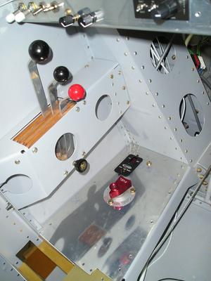 I installed a CO Guardian CO detector this week. It sits on the right side of the cockpit, ahead of the fuel selector. It should have been a fairly quick installation, but I had to buy a soldering iron to solder the wires onto the switch, as my soldering gun isn't suited to delicate work. The first soldering iron I bought turned out to be a cheap piece of junk, so I ran around to all the local electronics stores and ended up finding a Weller WLC-100 soldering station on sale. It seems like it will work well enough for the stuff I need to do.
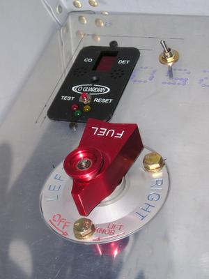 There is an LED display that will indicate the CO concentration. The CO monitor will beep continuously if the CO exceeds a its warning threshold. The switch to its right allows it to be switched off in case it ever goes crazy for no good reason.
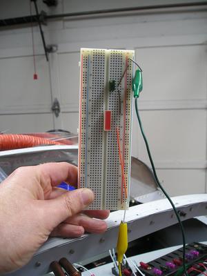 I also did some messing around with a potential annunciator panel solution, an LED light bar from Stanley. I rigged up a bread board test article, now I need to get a sunny day to see how visible they are.
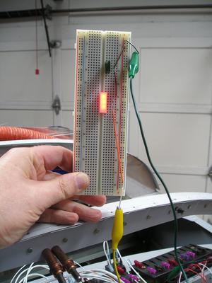 LED light bar illuminated.
