Rear Seat Riser - Metal Bashing Completed
- Details
- Written by Kevin Horton
- Hits: 4259
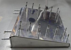 I finished up the metal bashing and drilling on the rear seat riser last night. Tonight I deburred and dimpled the holes. This shot was taken before I dimpled the holes. You can see the shim I needed at the front end of the rib on the left end of the wedge. I needed the shim because the one inch wide bevel at the front turned out wider on the left end than the right. Grumble grumble.
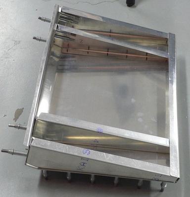 Here you see the bottom of the rear seat riser. The plans call for four ribs, and a width of 17 inches. At first glance, you would have the ribs evenly spaced. But that would have none of the ribs lining up with the ribs that support the cockpit floor. I moved the two inner ribs further apart, so they will lay right on top of the two ribs that run under the rear seat. That seemed much more sensible. It also makes a small area under the middle of the rear seat riser that I can use for storage. The length of unsupported 0.032 skin between the ribs is no wider than the width of unsupported 0.032 floor skin that the seat cushion is designed to sit on.
I've still got to mount a piece of hinge on the back to secure it in place, but I need to mess around in the rear cockpit to figure out the mounting details. So, that'll wait a day or two until we break out of this cold snap. I'll prime the parts and assemble them once it warms up in the spring.
Instrument Panel Painted
- Details
- Written by Kevin Horton
- Hits: 2816
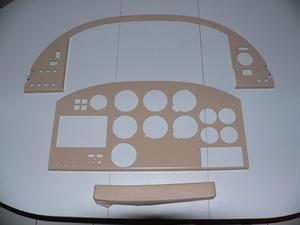 I picked up the instrument panel from the paint shop today. They did a great job! The finish is very slightly shinier than I wanted though - I'll see how it is once I put it in the aircraft and turn on the night flood lights.
The long brown rectangle below the instrument panel is one of the padded armrests that I wanted them to match with the paint colour. They did a great job there.
Back Home Again
- Details
- Written by Kevin Horton
- Hits: 3294
It's been a long week, but I got home early this evening. I've been in Wichita doing Enhanced Vision System (EVS) testing on the prototype Bombardier Global 5000. EVS has in infra-red camera that displays an image in the Heads Up Display (HUD). EVS offers two potential advantages: ability to see what is ahead during night operations, and the possible ability to see the approach and runway lights earlier in low visibility. The concept for low visibility operations is that if you can see the approach lights prior to reaching the approach minima, you can continue descent to 100 ft above the runway. At 100 ft above the runway, the pilot must be able to see the threshold or touchdown zone markings or lights with the naked eye, or a missed approach must be made (Note: all of the above is valid in the US only).
We're only part way through the planned EVS testing, and so far we've found some conditions where the EVS is no better than the naked eye, and other conditions where the EVS would allow landings to be accomplished that would have been missed approaches without it.
 And here we have a large group of Smurfs. No, its the EVS flight test crew. We had test pilots and flight test engineers from Bombardier, Transport Canada and the FAA, an Operational Standards pilot from Transport Canada, and an Aircraft Evaluation Group pilot from the FAA (the FAA AEG pilot was not available for this flight - we had a second TC Operational Standards pilot instead).
Rear Seat Riser
- Details
- Written by Kevin Horton
- Hits: 5479
I thought I was finished with the new instrument panel last weekend, but I discovered several minor issues that needed sorting out when I took out the microscope. I had to rework two nutplates that were hitting the mounting angle on the fixed part of the panel, and I needed to clean up quite a few rough edges. I finally dropped the fixed and removable panels off at the paint shop on Wednesday. I'll pick them up on the week of 17 Jan.
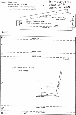 I started working on the rear seat riser on Wednesday night. The rear seat riser is a platform that lifts the rear seat cushion about three inches off the floor at the front, and slants back to be about 1.25 inches high at the rear (rear seat riser plans). I made a trial plywood rear seat riser in Oct 2003 to confirm the dimensions, and learned that I needed to make it a bit lower if I wanted to take Jim Manton (one of the other test pilots at work) in the back seat. I made it a half inch lower than the plans called for. If that doesn't give him enough head room, I'll pull it out when I fly with him. I'll probably also insert a one-inch balsa spacer between the seat riser and the seat cushion when Terry rides in back.
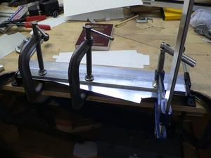 Wednesday I got the various parts laid out on a sheet of aluminum, cut them out and deburred them. Thursday I pulled out my cheap sheet metal brake, played with some scrap aluminum to figure out how it worked, then bent up the first rib. Yesterday I bent up the other three ribs, and got three of five bends done on the big piece of sheet that makes the top. It really made my head hurt to sort out the bend allowances and setbacks (www.tpub.com), to be sure to get the ribs the size I wanted after making the bends in the sheet metal, but it all worked out very well in the end.
I'm recording how I did this here, so I don't have to strain my brain so much the next time I have to bend some sheet metal parts to a desired size.
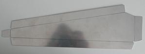 The lines on the rib blank mark the desired location of the outside edges of the part, after all bends are complete.
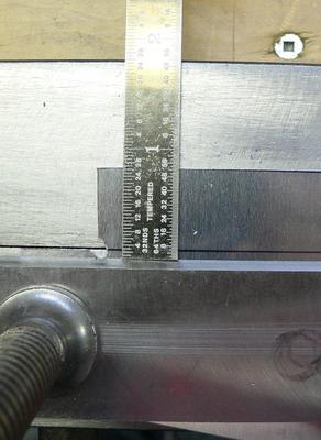 The sheet metal brake is clamped to the workbench, with the movable part facing away. The first bend is made with the flange facing away. The line on the blank is lined up with the break between the two parts of the sheet metal brake. The metal bar is placed back from the line, with the distance between the line and the edge of the metal bar equal to the material thickness plus the desired bend radius. In this case I used 0.032" thick material, and I wanted a 0.063 bend radius, so the bar was clamped 0.095" from the line, which equals 3/32".
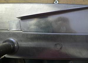 The second bend was a lot more complicated to sort out, as I had to turn the part the other way, or the first bend would hit the clamping bar. I had to dig into the Standard Aircraft Handbook to find a chart on bend allowances. It really made my head hurt, but I eventually decided that I needed to offset the line on the part from the brake pivot line by a distance equal to the bend allowance (from the chart in the Standard Aircraft Handbook), less the total of bend radius plus material thickness. The clamping bar had to be set the same distance from the brake pivot as before, as the desired bend radius was the same.
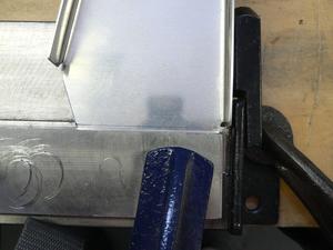 The third bend was the larger end. I had to slip the clamping bar as far to one side as possible, to make room for the other flange to go during the bending process. The last bend was the small end, and was done with hand tools.
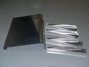 Things went quite well, until the fourth bend on the large piece of sheet that forms the top of the seat riser. I'm not sure exactly what happened, but that bend ended up a bit skewed. It is OK at one side, but the other side is out by about 0.10". Grrr. :( I stopped for the day, frustrated.
I was tempted to chuck it on the scrap pile, and start over. But I don't have a spare piece of aluminum laying around, and I am pushing this cheap brake pretty hard to do these bends. It takes a lot of force to bend a piece of 0.032 along a 17" bend. There is so much force that the clamped bar tends to slide, which is perhaps how I screwed up that bend. I can't be sure to get a better job on all five bends next time. The rear seat riser can't really be seen unless you lift the seat cushion, the error is not that big, and it won't affect the structural integrity, or how the rear seat riser functions. So, I'll use it as is, with some shims, I think.
I've got a 6 AM flight tomorrow morning to Chicago, and then Wichita. I'll be gone for the week, so I'll get back at this sometime next weekend.
RadioRax Avionics Mounting System
- Details
- Written by Kevin Horton
- Hits: 5002
I saw a glowing endorsement of the RadioRax avionics tray mounting system on the Aeroelectric List today. I had never heard of RadioRax, so I did some Googling. Aircraft Spruce has provided a better overview than the one on the RadioRax site.
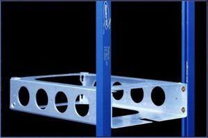 The RadioRax system uses beefy aluminum extrusions to secure the avionics tray to the instrument panel. The extrusions are slotted, so the trays can be moved vertically to facilitate avionics upgrades. I'm already pondering future avionics upgrades, so I may eventually wish I had used the RadioRax system. The means of securing the trays to the extrusions is supposedly strong enough that no supports are needed on the other end of the trays. RadioRax did a torture test with an avionics rack complete with avionics boxes mounted in a paint shaker. They had to use tape to hold the avionics boxes in the trays, as the shaking destroyed the avionics manufacturer's tray-to-unit fasteners. But the tray mounting system supposedly stood up to the paint shaker abuse without any movement between the rails and the trays.
I don't know whether I would have used the RadioRax system or not, if I had been aware of it. But, if I ever do an avionics upgrade, I'll probably wish I had used it.
Two New Forums
- Details
- Written by Kevin Horton
- Hits: 3963
Two new web forums have recently appeared, for those who need ways to spend even more time in front of the computer, instead of in the workshop :). WingsForum.com was the first one to come on the scene. It has sections for most major types of homebuilt aircraft, including RVs. It is too early to say whether it will reach a critical mass or not. I volunteered to moderate its Flight Test forum, but it hasn't exactly taken off yet, as the one lonely post was made by yours truly.
A few days after I learned about WingsForum.com, Doug Reeves added the VansAirForce Forums to the Vans Air Force World Wide Wing. The VansAirForce Forums have attracted a lot of interest, as Doug runs several very busy RV-related Yahoo Groups.
