I plan to occasional fly IFR, so I wanted a reliable electrical system to power navigation equipment, etc. My electrical system design is based on those proposed by Bob Nuckolls at the Aeroelectric Connection . Bob has been working in the field of aircraft electrical systems for many years. Most of his work has been on type certificated aircraft, but he was chosen to design the electrical system for the Voyager non-stop around the world aircraft. I liked Bob's design philosophy that emphasized a failure tolerant design, such that no single failure should cause the pilot to break a sweat.
Bob generously has provided a lot of information for builders on his web site. His suggested electric system designs provide a good starting point for homebuilders. I particularly liked his concept of an "all electric aircraft on a budget"
Read on for more.
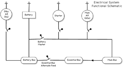
Electrical System Block Diagram

The important features of the electrical system of my RV-8 are:
1. Standby alternator - I decided to install a B&C Specialties 8 amp Standby Alternator instead of a vacuum pump. All my gyros will be electrically powered, and the standby alternator will provide power if the main alternator fails.
2. Battery Bus - this bus is always powered, even if the Battery Master switch is OFF. If I have a major smoke in the *censored*pit emergency, I can shut down the whole electrical system except for the battery bus. The turn coordinator and electronic ignition will still be powered (these items also have switches that can be used to kill their power when required).
3. Essential Bus - This bus powers the items that are needed to fly an IFR flight - gyros, navigation and communications equipment. Normally, it is powered from the main bus through a diode (the diode is there to prevent power from flowing in the other direction if the essential bus is powered, but the main bus is not).
4. Main Bus - This bus carries items that are not strictly required to continue the flight, such as pitot heat, landing light, wing leveler, electrically heated vest for the back seater, etc).
If the main alternator fails, and I need to conserve power, I will turn the Essential Bus Alternate Feed switch to ON, turn the Battery Master to OFF, and turn the Standby Alternator to ON. This will shed the items on the Main Bus, reducing the electrical load down to less than the 8 amps that the Standby Alternator produces.
I built up the various large cables that feed power from the battery to the main power bus and to the starter. In late-October, I powered up the main buses for the first "smoke check". No smoke! Since then I have gradually installed the rest of the main portions of the electrical system, and connected it up to many of the things that it feeds.
You can see the electrical system diagrams on-line.