The RV series have a fibreglas engine cowling, split into top and bottom pieces. The plans show that long pieces of piano hinge are used to hold the cowl to the firewall, and at the split line between the two halves. The top cowl is removed by pulling the hinge pin that joins the two halves together, then reaching in through the oil filler door and pulling the pins that hold the top half to the firewall. The top piece is then removed, allowing easy access to the hinge pins that secure the bottom half. Many builders have had problems with eyes breaking off the piano hinge. Others have flown over 1000 hours without problems. Scott McDaniels, one of the builders in Van's prototype shop, says the key is to ensure the cowl will fit in place without having to force it into position - i.e. ensure there is no preload on the hinges. Some builders have decided not to use the hinges, due to the reports of problems. However, I want to be able to remove the cowling quickly, as that will promote frequent inspections, so I decided to try the hinges.
 Like all the other fibreglas parts, the cowl halves have extra material around the edges that must be trimmed to fit.
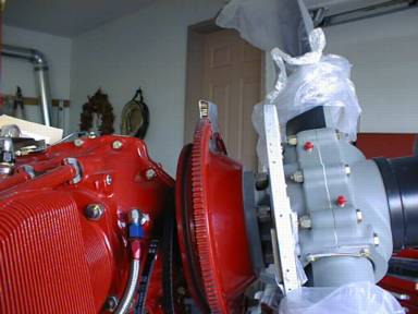
The process starts by fitting the piano hinges at the firewall. The piano hinges attach with the rivets that fasten the fuselage skins to the firewall, so those rivets haven't been installed yet. You have to remove the clecos that go in those holes, put the hinge in behind, and drill though the holes into the hinge, clecoing as you go. I had two problems:
- the holes in the fuselage skin and firewall didn't want to stay perfectly aligned once the clecos were removed, and
- the edge of the hinge material didn't want to stay tight against the face of the firewall, so the holes I was drilling had a tendency to get closer and closer to the edge of the hinge as I went along.
Tip - I stumbled upon a couple of ideas that helped me through these problems:
- I used a few NAS1097 "cheater" rivets to keep the holes in the fuselage skins and firewall in alignment. These rivets have a very small head. I simply slipped a rivet in about every fourth hole, with the head on the inside. The head is thin enough that the hinge still sat reasonably well against the firewall flange. Once I drilled and clecoed a few holes in the hinge I removed the rivets from the holes.
- I had much better luck drilling the hinge if I started in the middle. That way once you had the hinge tight against the firewall face, and drilled and clecoed the first hole, it really couldn't move on you.
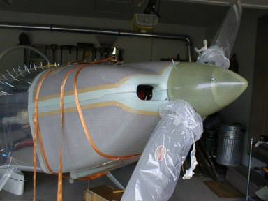
 The upper cowl is fitted first. I taped a spacer on top of the ring gear to hold the front of the cowl at the proper height. The spacer was made of pieces of popsicle stick, so I could easily adjust the thickness until I got it just right. I made 3/4 inch thick spacers to put between the front of the cowl and the rear face of the spinner rear bulkhead. This gave 1/4 inch clearance between the rear edge of the spinner and the front face of the cowling.
Tip - I clamped the front face of the cowling to the spinner bulkhead, then used my digital level to eyeball against the upper edges of the air inlet holes to be sure the cowling was going on level with the rest of the aircraft. I found that if I held the level flat against the spinner front bulkhead, lined up with the centreline of the aircraft, I could get very repeatable measurements of the angle of the cowling. I checked the angle of the fuselage in the seat rail area, and was able to get the cowling exactly the same angle.
After the cowling was secured in the right location, I trimmed the rear edge to fit, then drilled three holes from the cowling to the hinge to fix it in position.
Then I attacked the lower cowling. There is lots of extra material on all edges, so at first it wasn't possible to get the lower cowling anywhere close to the correct vertical location. I trimmed a little bit off at a time, working to get a good fit between to the lower and upper cowling where they meet at the front. The sides can simply overlap for now, but the front must butt up against each other.